Other Parts Discussed in Thread: TCA9555, TCA9534A, , EK-TM4C129EXL
Hi,
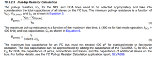
We are running a direct communication with TCA9555 I2C chip. The chip is at 4 inch distance on same board. The chip is directly connected without any buffer or isolators. We have 4.75kR pull ups. The firmware I have written is tested in another project and works fine when communicating to TCA9534A chip. The communication is at 100kHz.
We see randomly one of the clock pulse will go half-way and would appear to be spike. We know this is not a spike but an abnormal clock pulse because when we measure the period of the pulse with its neighbor pulses it is same period. When we see this spiky-clock pulse, the TCA9555 chip will not release the SDO line, which I assume because the TCA9555 when doesnt recognize the spiky-half-way clock pulse, the chip expects one more pulse from microntroller and hence doesn't release the SDO line.
Additionally, we also noted some pulses on the SDO data line are not normal either. See the two snapshots bellow.
First Snapshot shoes one of the clock pulse is half-way and appears as a spike and hence SDO line will not transition from Low to High.

The following second snapshot shows all clock pulses are correct and hence the SDO line is released however some data pulses on the SDO line seems not normal.

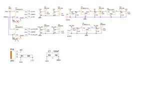
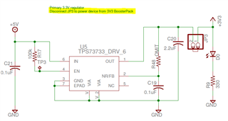
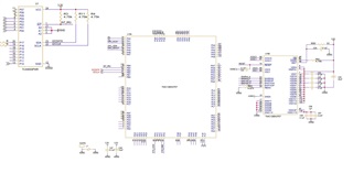
Following is the schematic picture.
The i2c initialization, i2c_read code is bellow;
void Internal_I2C_Init(void)
{
    //I2C0 Module initialization
    ROM_SysCtlPeripheralDisable(SYSCTL_PERIPH_I2C0);
    SysCtlDelay(100);
    ROM_SysCtlPeripheralReset(SYSCTL_PERIPH_I2C0);
    SysCtlDelay(100);
    ROM_SysCtlPeripheralEnable(SYSCTL_PERIPH_I2C0);

    while(!SysCtlPeripheralReady(SYSCTL_PERIPH_I2C0)){} //Wait for I2C0 Module to stabilize
    I2CMasterEnable(IOChip_I2C_BASE);
    GPIOPinConfigure(GPIO_PB2_I2C0SCL);
    GPIOPinConfigure(GPIO_PB3_I2C0SDA);
    GPIOPinTypeI2CSCL(IOChip_I2C_BASE, IOChip_I2C_SCL_PIN);
    GPIOPinTypeI2C(IOChip_I2C_BASE, IOChip_I2C_SDA_PIN);
    ROM_I2CMasterInitExpClk(IOChip_I2C_BASE, sys_clock, I2C_100kHz_CLOCK);

}

uint32_t I2C_read(uint32_t ulBase, uint8_t chip_address, uint8_t internal_address)
{
    //Send Chip Hardware Address and Internal address of the register to write the date
    ROM_I2CMasterSlaveAddrSet(ulBase, chip_address, false); // Specify slave address with read request set to false
    ROM_I2CMasterDataPut(ulBase, internal_address); //Place the Internal register address
    ROM_I2CMasterControl(ulBase, I2C_MASTER_CMD_SINGLE_SEND); // Initiate send of 1Byte character from Master to Slave
    while (!(ROM_I2CMasterBusy(ulBase))); //Wait till end of transaction
    while(I2CMasterBusy(ulBase)); // not busy

    //Receive Data
    ROM_I2CMasterSlaveAddrSet(ulBase, chip_address, true); // Specify slave address with read request set to true
    ROM_I2CMasterControl(ulBase, I2C_MASTER_CMD_SINGLE_RECEIVE);// Initiate send of character from Master to Slave
    while (!(ROM_I2CMasterBusy(ulBase))); //Wait till end of transaction
    while(I2CMasterBusy(ulBase));

    //Read Receive Data from FIFO
    return (ROM_I2CMasterDataGet (ulBase)); //Read from FIFO
}
Thank you very much for your time.