Part Number: TM4C129DNCPDT
Other Parts Discussed in Thread: EK-TM4C1294XL
Hi,
I am working on TM4C129DNCPDT and TI-RTOS and Tivaware driver lib.
How to setup timer counter increment every 1us? we don't want any interrupt, we want to pull the counter value.
For setup
void init_timerCounter()
{
SysCtlPeripheralEnable(SYSCTL_PERIPH_TIMER0);
while(!SysCtlPeripheralReady(SYSCTL_PERIPH_TIMER0))
{
}
TimerClockSourceSet(TIMER_B, TIMER_CLOCK_SYSTEM);
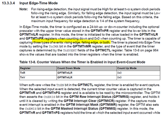
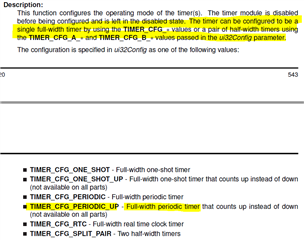
TimerConfigure(TIMER_B, TIMER_CFG_PERIODIC_UP);
TimerLoadSet(TIMER0_BASE,TIMER_B,ui32SysClock/1000);
TimerPrescaleSet(TIMER0_BASE,TIMER_B,16);
TimerIntDisable(TIMER0_BASE,TIMER_B);
TimerEnable(TIMER0_BASE, TIMER_B);
}
For counter value get
uint32_t = time1;
time1 = TimerValueGet(TIMER0_BASE, TIMER_B);
I am getting some run time error.
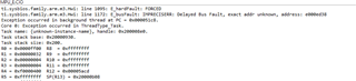
Maybe i am doing something wrong.
Regards,
Sumit