Part Number: MSPM0G1106
Other Parts Discussed in Thread: SYSCONFIG, MSPM0L1306, MSPM0G3505, MSPM0G3506, MSPM0G3507
I am playing with sysconfig in the cloud, I’m not sure if I’m not using it right or there is a bug.
When I add an ADC to my part, it adds 2 pins for debug and 1 for the ADC.
Then I tell it I want it to do a sequence of 8 not a sample, number of pins do not change.
Then I go through and change the channels from all being 0 to the next sequential
- why isn’t this the default? I would think it should try to find available channel/pins and use them, not the same pin over and over.
When I’m going through the channels, as I change them from channel 0 to channel N I see the pin counts go up. This is expected.
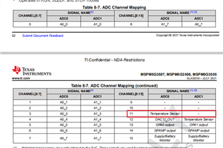
When I get to assign channel 4, I get an error, this channel must not exist? I guess this is ok?
2. note that the channel list don't even give the choices of 9 and 10, should some of these other channels not show up as choices? is all this working as expected?
these assigns work as expected: channels 0,1,2,3
These give a resource error: channels 4,5,6, (so i skip them)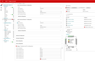
then these assigns work as expected channel 7,8
now when i try channel 9 for my next one, i get no error, and the pin is not assigned.
2) what is going on here?
But when I assign to 11, I don’t get an error and the pin count doesn’t go up.
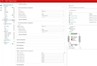
pinmux doesn't show channel 11, and there are no errors, it just does nothing?
3. once i have a sys config is there a "report" or schematic that shows what needs to be connected to all the pins?