We are currently using two TIC10024QDCPRQ1 MSDI.
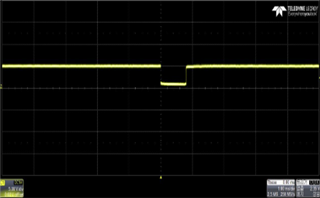
When using two, there is a change in waveform (HIGH -> LOW -> HIGH) as shown below at the INT pin of the device without changing the value of IN0 to IN23.
If only one is used, the value of HIGH is maintained at the INT pin of the device without changing the value of IN0 to IN23.
If there is no change in the value of IN0 to IN23 even if two are used, I want the operation that the HIGH value is maintained at the INT pin.
Inquiries are as follows:
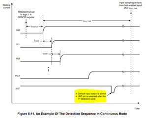
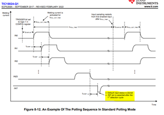
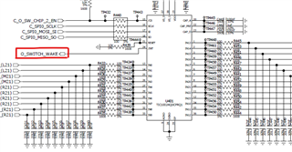
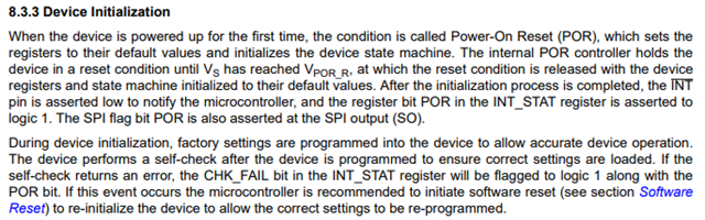
1. In the case of the /INT pin, it is written that it is allocated as LOW when input is detected from the IN element of MSDI. Is there any other condition that can change the /INT pin to LOW?
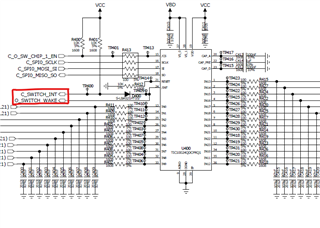
2. Is there any effect on the /INT pin when using 2 MSDI?
3. How to debug the phenomenon that /INT pin goes low when 2 MSDI are connected