This thread has been locked.

If you have a related question, please click the "Ask a related question" button in the top right corner. The newly created question will be automatically linked to this question.

EK-TM4C123GXL: How to use debug mode with allowing command serially using cutecom ?

Part Number: EK-TM4C123GXL

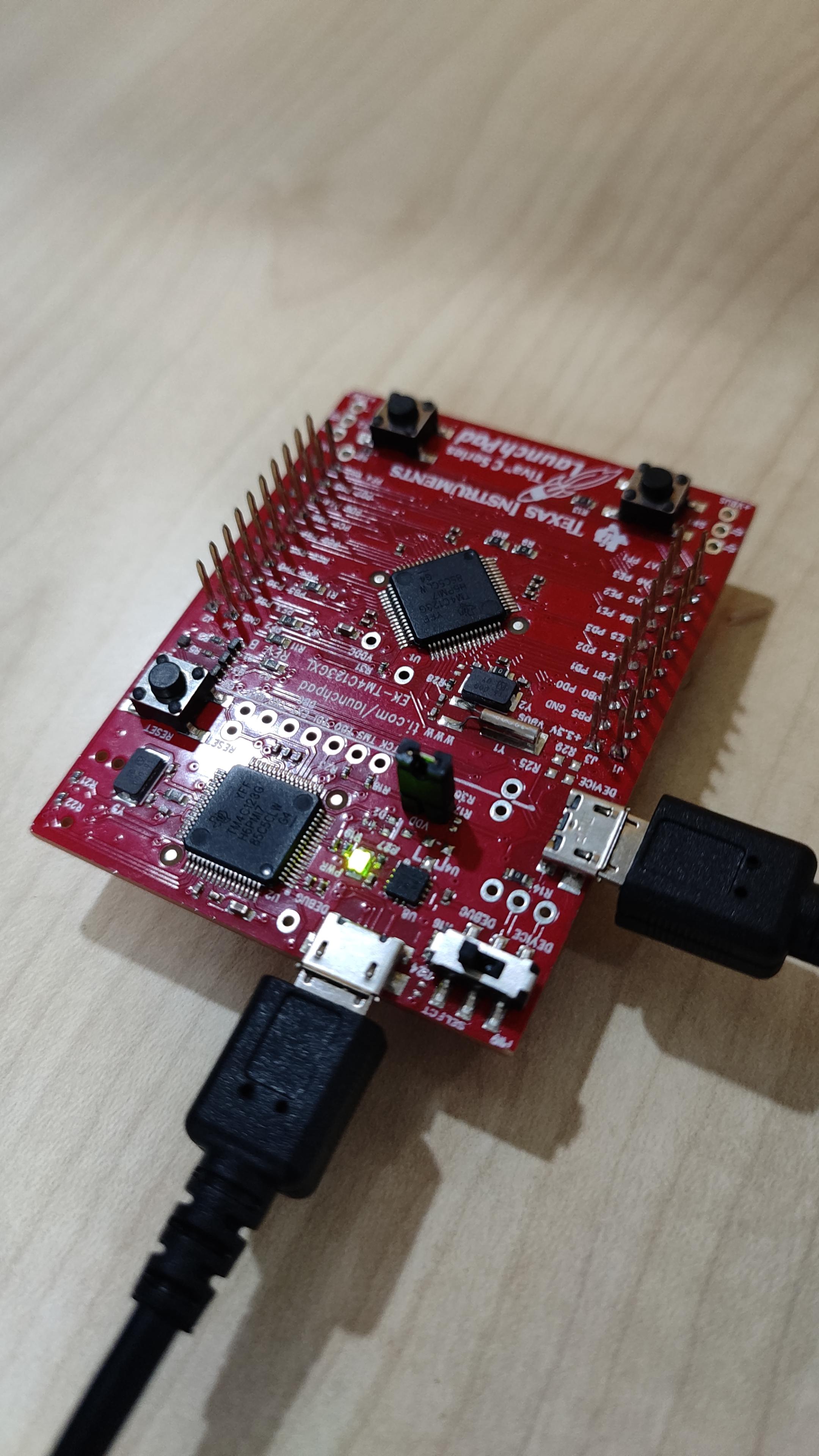
I have seen that this board allows the debug mode front port. and it also allows the send data to this board using port available on left side of this board.

But i have find that i can do this thing at a one time.

What steps i needed to follow so i can use debug as well as command sending to this board from left side port ?

  • Hi,

      The front port is the USB debug port. The one on the left side is the USB device port. The debug port connects to the on-board ICDI debug probe for debugging the target. The device port on the left is for running USB application. What is your targeted application? If your application will involve using USB device port then you will connect another USB cable to the USB device port while you still connect to the USB debug port for supplying power to the board and as a means to download code, debug your project. 

      There are a few USB examples in TivaWare library. See below. For example, if you run the usb_dev_serial, the example turns the board into a virtual serial
    port when connected to the USB host system (your PC) where you can send/receive data  to/from it. You just need to open a terminal window to exchange data with the USB device as if it is a UART device. 

  • yes  my application is usb based application. But still same problem. how to resolve this issue ?

    because when debug usb port not connected at that time i can easily able to send command using cutecom. but when i try to use debug application at that time it not send output on cutecom and not allow properly debug application with sending command on cutecom.

  • Which usb example did you run?

    If you run usb_dev_serial example then there will be two virtual COM ports enumerated. Do you see that? I'm not familiar with cutecom and neither linux. But in windows you will see two different COM ports. You need to make sure one is enumerated for the USB device port and another one is enumerated for the ICDI debug port. When you send command on cutecom you need to select the right COM port number.  

  • Above i attached image. is there any mistake i done or not ? because still after starting debug mode application of mine is not working.

  • First of all, you are showing two identical pictures.

    - Are you having two boards or just one board? 

    - If you only have one board, I suppose you connect both ports on the board to your host machine, right? Your picture does not show where they are connected to. With that said, it is correct that that you need one cable connected to the USB debug port and another cable connected to the USB device port in order to run usb_dev_serial example. 

    - I will suggest you first run the example on the Windows PC. Make sure it works as expected. The usb_dev_serial example is supposed to work right out of the box. Run on a Windows machine will help you isolate the problem if the current problem is Linux related. I'm not well versed in Linux commands but I think you can use ls /dev/tty* to show the connected port. 

    https://www.cyberciti.biz/faq/find-out-linux-serial-ports-with-setserial/

  • Sorry to repeat again. i am using linux with CCS. I am running my application not your given example code. Because i have to find where i made the mistake.

    i don't know but when i debug at that time i am not getting data into USBRingBufRead.

  • Hi,

      I really suggest you start with a usb example to get a feel of the usb library. If you can get it to work, you can reference it to build your own application.