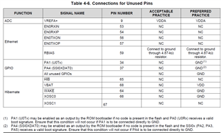
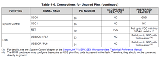
I am connecting up this part in my design. We are not using Ethernet. How shall I connect those pins on the part?
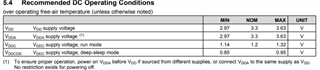
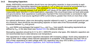
On the development board I see Vddc and its return Vss, but I cannot see where this supply comes from and how it is to be connected.
I am not using the A/D converter. How shall Vdda be connected?
Lastly, I am not using hibernate nor the battery, how should those pins be connected for proper operation?
Thank you for your help.