This thread has been locked.

If you have a related question, please click the "Ask a related question" button in the top right corner. The newly created question will be automatically linked to this question.

TM4C1294NCPDT: "I2C Busy" vs "I2C Busy Busy"?

Part Number: TM4C1294NCPDT

We're having an odd issue with a custom board using a TM4C1294NCPDT.  We're using I2C Channel 9 to talk to 8 different slave sensors.  When our board powers up, I have the TM4C perform an initialization step on the sensors to make sure communication is working.  After this, status from the sensors is read every 80 milliseconds.  This works fine in the beginning but eventually (anywhere from a few seconds to an hour) communication completely stops. 

We have an oscilloscope hooked up to the SCL and SDA lines.  When communication stops, both the SCL and SDA lines remain high indefinitely despite the firmware continuing to call the typical series of I2C Tiva Ware functions to read data such as:  I2CMasterSlaveAddrSet, MAP_I2CMasterDataPut, MAP_I2CMasterControl, etc.

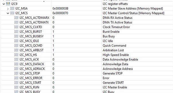
Even after calling MAP_I2CMasterControl to initiate a I2C_MASTER_CMD_BURST_SEND_START the lines SCL and SDA lines both remain high.  I set a breakpoint there to see what the I2C register values, I've attached them in the below image.

You'll notice I2C_MCS_BUSY is false yet I2C_MCS_BUSBY is true.  The datasheet (SPMS433B) explains I2C_MCS_BUSY as relating to the "controller" (e.g. "the controller is either idle or busy") and the I2C_MCS_BUSBY as relating to the "bus" (e.g. "the bus is ide or busy").

So, in my case, based on the register values below, the controller is not busy, but the bus is.  However, because of the oscilloscope, we're certain both lines are high, which, in my experience, means the bus is not busy.  Anyone know what might be going on?


  • Hi,

      I have a few questions:

      - Can you replicate the problem on the LaunchPad?

      - Does it matter if you only have one slave sensor or 8 sensors? In another word, can you replicate the problem with only one sensor connected?

      - When SDA and SCL are held high, can you tell if that happens in the middle of a transaction or that is after the STOP bit is asserted?

      - Can you show the scope cap or better yet a logic analyzer capture when both SDA and SCL are held high?

      - Can you show your code where you do the read?

      - If you add the below highlighted in red, will it make a difference? Below is an example sequence to read an I2C device. Basically, it is to first poll for not busy and then busy. 

    void
    I2CReadCommand(uint32_t * pui32DataRx)
    {
    //
    // Modify the data direction to true, so that seeing the address will
    // indicate that the I2C Master is initiating a read from the slave.
    //
    MAP_I2CMasterSlaveAddrSet(I2C7_BASE, SHT21_I2C_ADDRESS, true);

    //
    // Setup for first read. Use I2C_MASTER_CMD_BURST_RECEIVE_START
    // to start a burst mode read. The I2C master continues to own
    // the bus at the end of this transaction.
    //
    MAP_I2CMasterControl(I2C7_BASE, I2C_MASTER_CMD_BURST_RECEIVE_START);

    //
    // Wait until master module is done transferring.
    // The I2C module has a delay in setting the Busy flag in the register so
    // there needs to be a delay before checking the Busy bit. The below loops
    // wait until the Busy flag is set, and then wait until it is cleared to
    // indicate that the transaction is complete. This can take up to 633 CPU
    // cycles @ 100 kbit I2C Baud Rate and 120 MHz System Clock. Therefore, a
    // while loop is used instead of SysCtlDelay.
    //
    while(!MAP_I2CMasterBusy(I2C7_BASE))
    {
    }
    while(MAP_I2CMasterBusy(I2C7_BASE))
    {
    }

    //
    // Read the first byte data from the slave.
    //
    pui32DataRx[0] = MAP_I2CMasterDataGet(I2C7_BASE);

    //
    // Setup for the second read. Use I2C_MASTER_CMD_BURST_RECEIVE_CONT
    // to continue the burst mode read. The I2C master continues to own
    // the bus at the end of this transaction.
    //
    MAP_I2CMasterControl(I2C7_BASE, I2C_MASTER_CMD_BURST_RECEIVE_CONT);

    //
    // Wait until master module is done transferring.
    //
    while(!MAP_I2CMasterBusy(I2C7_BASE))
    {
    }
    while(MAP_I2CMasterBusy(I2C7_BASE))
    {
    }

    //
    // Read the second byte data from the slave.
    //
    pui32DataRx[1] = MAP_I2CMasterDataGet(I2C7_BASE);

    //
    // Setup for the third read. Use I2C_MASTER_CMD_BURST_RECEIVE_FINISH
    // to terminate the I2C transaction. At the end of this transaction,
    // the STOP bit will be issued and the I2C bus is returned to the
    // Idle state.
    //
    MAP_I2CMasterControl(I2C7_BASE, I2C_MASTER_CMD_BURST_RECEIVE_FINISH);

    //
    // Wait until master module is done transferring.
    //
    while(!MAP_I2CMasterBusy(I2C7_BASE))
    {
    }
    while(MAP_I2CMasterBusy(I2C7_BASE))
    {
    }

    //
    // Note the third 8-bit data is the checksum byte. It will be
    // left to the users as an exercise if they want to verify if the
    // checksum is correct.
    pui32DataRx[2] = MAP_I2CMasterDataGet(I2C7_BASE);
    }


  • Hi Terence,

      I have not heard back from you. I assume your issue is resolved. If not, please write back to this post and the post will automatically change the status to open and I will be notified.