This thread has been locked.

If you have a related question, please click the "Ask a related question" button in the top right corner. The newly created question will be automatically linked to this question.

TMS570LC4357: Trying to get MOSI to change on the SPI bus before clock changes

Part Number: TMS570LC4357
Other Parts Discussed in Thread: HALCOGEN

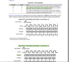
On the TMS570 processor we have a chip we are communicating with that seems to need the MOSI line to lead the clock, is there a field in the SPI controller to adjust that?  

  • Hi Den,

    Started working on your issue and will provide an update as soon as possible.

    --

    Thanks & regards,
    Jagadish.

  • Hi Den,

    Are you looking for SPI Mode 1, 

    In this mode only the output data will lead by half cycle than raising edge of SCLK.

    To enable this mode, in halcogen have to enable the polarity bit in data format section

    --

    Thanks & regards,
    Jagadish.

  • no not quite what I was looking for, I have a datasheet for a chip that I am trying to communicate with that says MOSI must be held for 9 nanoseconds after clock, their support says this requirement must be met, and I am checking if there is a software way of doing it. In the timing diagram Th(SO) time is what I am trying to meet.

    With The TMS570 we checked the timing of this in different modes and there is a slight variation and is there some type of way to control it> 

    The plots below show that the TMS570 (clock in yellow and MOSI in blue) changing at almost the same time, and we need it to change like the second scope plot where the clock changes first before the MOSI changes. 

    So this is not a mode shift or a phase delay, is there some other type of control for it?

    The way we are going to test is is by changing the SPI lines to GPIO and code everything, but we would prefer to use the automated SPI process.

  • Hi Dan,

    The parameter you are mentioning is the 5th parameter in datasheet.

    It is nothing but a time for which data is valid after sampling edge of the CLK.

    tv(SPCL-SIMO)M = 0.5tc(SPC)M – tf(SPC) – 4

    tv(SPCH-SIMO)M = 0.5tc(SPC)M – tr(SPC) – 4

    In this formula 

    tv = valid time

    tc = cycle time

    tf = falling time

    tr = raising time 

    So valid time will be depending on cycle time and either raising or falling time.

    If your SPI operate with highest frequency of 25Mhz then cycle time will be 40ns

    so, after we are substituting it in above formula the minimum valid time of SPI will be as below

    tv(SPCL-SIMO)M = 16 – tf(SPC) 

    tv(SPCH-SIMO)M = 16 - tr(SPC)

    So, at this frequency to meet your requirement 9 nanoseconds the rise time or fall time should not be more than 7nanoseconds.

    There is no software configuration to increase tv, we have to make sure rise time should be less than 7 nanoseconds or else we have to reduce the frequency so that tv time will get increased.

    --

    Thanks & regards,
    Jagadish.