This thread has been locked.

If you have a related question, please click the "Ask a related question" button in the top right corner. The newly created question will be automatically linked to this question.

TM4C1294NCPDT: CAN Communication issue

Part Number: TM4C1294NCPDT

Dear Sir.,

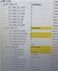
We are using TM4C1294NCPDT microcontroller and CAN1 communication.We are communicating two PCB with CAN communication. We received CAN Communication fault error randomly. We could not able to run, please let me know if i add any initialization for CAN configuration.

This is for 1st PCB CAN1 initialization,(Transmitting)

SysCtlPeripheralEnable(SYSCTL_PERIPH_CAN1);
CANInit(CAN1_BASE);
CANBitRateSet(CAN1_BASE, SysClkFreq, 500000);
CANIntEnable(CAN1_BASE, CAN_INT_MASTER | CAN_INT_ERROR | CAN_INT_STATUS);
IntEnable(INT_CAN1);
CANEnable(CAN1_BASE);

CAN1MsgRx.ui32MsgID = CAN1RXID;
CAN1MsgRx.ui32MsgIDMask = 0;
CAN1MsgRx.ui32Flags = MSG_OBJ_RX_INT_ENABLE | MSG_OBJ_USE_ID_FILTER;
CAN1MsgRx.ui32MsgLen = sizeof(g_ui8CAN1RxData);
CANMessageSet(CAN1_BASE, CAN1RXOBJECT, &g_CAN1MsgRx, MSG_OBJ_TYPE_RX);

This is for 2nd PCB CAN1 initialization,(Receiving)

SysCtlPeripheralEnable(SYSCTL_PERIPH_GPIOB);
GPIOPinConfigure(GPIO_PB0_CAN1RX);
GPIOPinConfigure(GPIO_PB1_CAN1TX);
GPIOPinTypeCAN(GPIO_PORTB_BASE, GPIO_PIN_0 | GPIO_PIN_1);

SysCtlPeripheralEnable(SYSCTL_PERIPH_CAN1);
CANInit(CAN1_BASE);
//CANRetrySet(CAN1_BASE, false);
CANBitRateSet(CAN1_BASE, g_ui32SysClkFreq, 500000);
//CANIntRegister(CAN1_BASE, CAN1IntHandler);
CANIntEnable(CAN1_BASE, CAN_INT_MASTER | CAN_INT_ERROR | CAN_INT_STATUS);
IntEnable(INT_CAN1);
CANEnable(CAN1_BASE);


CAN1MsgRx.ui32MsgID = CAN1RXID;
CAN1MsgRx.ui32MsgIDMask = 0;
CAN1MsgRx.ui32Flags = MSG_OBJ_RX_INT_ENABLE | MSG_OBJ_USE_ID_FILTER;
CAN1MsgRx.ui32MsgLen = sizeof(g_ui8CAN1RxData);
CANMessageSet(CAN1_BASE, CAN1RXOBJECT, &g_CAN1MsgRx, MSG_OBJ_TYPE_RX);

If you need any information please let me know.

Thanks in advance.

  • Hi,

      I'm a bit confused. If you are transmitting for PCB1, then why are you setting the message object for RX?

    This is for 1st PCB CAN1 initialization,(Transmitting)

    SysCtlPeripheralEnable(SYSCTL_PERIPH_CAN1);
    CANInit(CAN1_BASE);
    CANBitRateSet(CAN1_BASE, SysClkFreq, 500000);
    CANIntEnable(CAN1_BASE, CAN_INT_MASTER | CAN_INT_ERROR | CAN_INT_STATUS);
    IntEnable(INT_CAN1);
    CANEnable(CAN1_BASE);

    CAN1MsgRx.ui32MsgID = CAN1RXID;
    CAN1MsgRx.ui32MsgIDMask = 0;
    CAN1MsgRx.ui32Flags = MSG_OBJ_RX_INT_ENABLE | MSG_OBJ_USE_ID_FILTER;
    CAN1MsgRx.ui32MsgLen = sizeof(g_ui8CAN1RxData);
    CANMessageSet(CAN1_BASE, CAN1RXOBJECT, &g_CAN1MsgRx, MSG_OBJ_TYPE_RX);

    Please refer to the CAN example in the folder C:\ti\TivaWare_C_Series-2.2.0.295\examples\peripherals\can. There are examples for TX and RX. 

  • HI.,

    Thank you for your reply.Actually the concept is PCB_1 is asking request to PCB_2(Transmitting). And PCB_2 sending reply to PCB_1(Receiving).The both PCB s are transmitting and receiving.PCB_1 receiving data from PCB_2 also. So we used Rx interrupt. Once we debug the code ,CAN_ERR shows 1.I mentioned in below screen shot for your reference.

    Thank you

  • Hi, 

    Actually the concept is PCB_1 is asking request to PCB_2(Transmitting). And PCB_2 sending reply to PCB_1(Receiving).The both PCB s are transmitting and receiving.PCB_1 receiving data from PCB_2 also.

     From your description, it seems that you want to generate a REMOTE frame. If that is the case you need to use something like below to start a remote frame.
    CANMessageSet(CAN0_BASE, 1, &sMsgObjectRx, MSG_OBJ_TYPE_TX_REMOTE);

      Also see below post which is helpfu with code snippet. https://e2e.ti.com/support/microcontrollers/arm-based-microcontrollers-group/arm-based-microcontrollers/f/arm-based-microcontrollers-forum/643158/ek-tm4c123gxl-read-a-remote-frame-via-can-bus?tisearch=e2e-sitesearch&keymatch=MSG_OBJ_TYPE_TX_REMOTE#

  • Thank you for your valuable response.

    PCB_1 send and Receive data from PCB_2.And PCB_2 send and Rx data from PCB_1.My assumption is,the error came from two cases right.

    case 1: PCB_1 didn't send data to PCB_2.

    case 2: PCB_2 didn't receive data from PCB_1.

    once i debug,if the CAN communication fault occurs CAN_ERR_EWARN=1 & CAN_EPASS=1.(Refer above screen shot)

    So i decided to change my code like,

    CANRetrySet(CAN1_BASE, true);

    i add (enable) this above peripheral in both PCB_1 and PCB_2.

    Please guide me is this correct action taken for CAN communication fault?

    And now i come into the your point:

    Once i changed CANMessageSet(CAN0_BASE, 1, &sMsgObjectRx, MSG_OBJ_TYPE_TX_REMOTE); this one It will be solve CAN error fault?

    And i will add this above peripheral in PCB_1 or PCB_2. otherwise i will add all transmitting or receiving areas?

    And i will try this and let you know.

    Please guide me for solving this CAN fault.If you need any information please let me know.

    Thanks in advance.

  • Hi,

     I don't know what caused the receive error counter to go up. Some errors was detected. However, the LEC bit field was showing 0 which is no error. You need to first answer the question if REMOTE FRAME is what you want for your application. Normally, In CAN protocol, if one node (PCB_1) wants to request data from another node (PCB_2) , it needs to send a REMOTE_FRAME, not DATA FRAME. Basically, a remote frame is broadcasted by a transmitter to request data from a specific node. What you had before, both nodes are set up with MSG_OBJ_TYPE_RX on the message object. No one is actually sending any message on the bus. That is what I see in your snippet of code unless you have other code that transmits data that is not shown in your upload. 

    Please use the logic analyzer or scope capture to see the traffic on the bus. It will provide more debugging information.