This thread has been locked.

If you have a related question, please click the "Ask a related question" button in the top right corner. The newly created question will be automatically linked to this question.

TM4C129DNCPDT: PWM Duty cycle increase

Part Number: TM4C129DNCPDT
Other Parts Discussed in Thread: EK-TM4C1294XL

Hi, 

 I am working Pulse generation with different width and interval. My PWM setup is generating 20us of pulse width and 70ms of interval.

void init_pwm()
{
SysCtlPeripheralEnable(SYSCTL_PERIPH_GPIOF); // system peripheral enable for GPIOF
SysCtlPeripheralEnable(SYSCTL_PERIPH_PWM0); // system peripheral enable for PWM0
// SysCtlPWMClockSet(SYSCTL_PWMDIV_1); // pwm clock set
PWMClockSet(PWM0_BASE, PWM_SYSCLK_DIV_64);
GPIOPinConfigure(GPIO_PF0_M0PWM0); // Gpio pin function configuration as a pwm
GPIOPinTypePWM(GPIO_PORTF_BASE,GPIO_PIN_0 ); // Gpio pin for pwm

while(!SysCtlPeripheralReady(SYSCTL_PERIPH_PWM0)) // wait for peripheral ready
{
// do nothing
}
PWMGenConfigure(PWM0_BASE,PWM_GEN_0,PWM_GEN_MODE_DOWN|PWM_GEN_MODE_NO_SYNC); // Pwm generation 0, down mode, no synchronization
PWMGenPeriodSet(PWM0_BASE, PWM_GEN_0, 4294967295); // pwm_generation 0, period set
PWMPulseWidthSet(PWM0_BASE, PWM_OUT_0, 36); // duty cycle
PWMOutputState(PWM0_BASE, PWM_OUT_0_BIT,true); // pwm output enable
PWMGenEnable(PWM0_BASE, PWM_GEN_0);

}

I want to generate 20us of pulse width 1S of interval. HOW to setup PWM Module?

Regards,

Sumit Chaulya

  • Hi,

    I want to generate 20us of pulse width 1S of interval. HOW to setup PWM Module?

      What type of PWM application is this that requires 1s of period? In many of PWM applications, the period is set up for kHz, not 1Hz. The PWM counter is only 16-bit. Even if you set the PWM clock divider to PWM_SYSCLK_DIV_64, the maximum period you can generate will be 1.875Mhz (120/64=1.875) based on a 120Mhz system clock. Of course, you can also use the PLL to generate a slower system clock but that still won't give you 1s of period. 

    PWMGenPeriodSet(PWM0_BASE, PWM_GEN_0, 4294967295); // pwm_generation 0, period set

    As explained above, the counter is only 16-bit which can take the maximum value of 0xFFFF or 65535 decimal value. You cannot load  4294967295 into a 16-bit counter. 

    The Timer module in PWM mode can give you a 24-bit counter. But that still won't give you a 1s period. 

    For general PWM setup, there is an example in C:\ti\TivaWare_C_Series-2.2.0.295\examples\boards\ek-tm4c1294xl\pwm_invert that shows you how to set up the period and duty cycle based on a divided PWM clock. 

  • Hi, Charles.

    Do you have any suggestions for generate the 20us of pulse width and 1s of pulse interval?

    Regards,

    Sumit 

  • HI,

      I can envision you try two timers to generate 20us duty and 1s period. You will setup one timer module that timeout in 1s and another timer that timeout in 20us. The 1s timeout is used to create a PWM period. The 20us timeout is used to toggle a GPIO pin. When the 1s timer timeout, it generates an interrupt. In the 1 second ISR, You will set a GPIO pin high and you will also launch the second timer in a one-shot timer mode of 20us. You will use the one-shot timer timeout to clear the GPIO pin. Note you don't need to wait for 20us in the 1 second ISR. You can set a flag so that you can toggle the GPIO inside the main() function.  

  • Hi, Charles.

           1.Can we set one-shot PWM?

            2. 1s interval from Pulse falling edge. 

    Regards,

    Sumit

  • Hi,

       1.Can we set one-shot PWM?

            2. 1s interval from Pulse falling edge. 

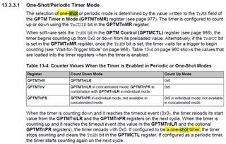
    No, you cannot do one-shot PWM. You can do one-shot Timer mode. Please refer to the datasheet for details. 

    You basically setup one 32-bit timer and another 16-bit timer. Let's say you combine Timer0_A and Timer0_B into one 32-bit timer to create the period. You will setup another timer like Timer1_A for the duty cycle generation. 

    When Timer0 expires (e.g. 1s) you will do two things in the ISR. 

      1. Set a GPIO pin.

      2. LaunchPad Timer1_A in one-shot mode. 

    When Timer1_A expires (e.g. 20us) you will clear the GPIO pin. 

    This is just an idea. You can refine the concept or come up with different approaches that best suit your application.