This thread has been locked.

If you have a related question, please click the "Ask a related question" button in the top right corner. The newly created question will be automatically linked to this question.

MSPM0G1106: debugger & header

Part Number: MSPM0G1106

I'm working on getting a launchpad and debugger from my FAE, but i'm trying to finish up some schematics for our own design as well.

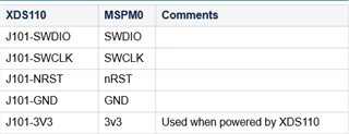
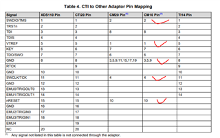
What debugger and connection/header should i use to program/debug the micro controller?

it seems that SWD is the expected method?

Does TI recommend a particular debugger?

It seems that SWD debuggers are fairly common, is it ok to non-ti with CCS?

  • it seems that SWD is the expected method?

    Yes

    Does TI recommend a particular debugger?

    XDS110 or J-Link

    It seems that SWD debuggers are fairly common, is it ok to non-ti with CCS?

    J-Link has been tested on our side

  • what connection/header is required for xds110?

  • the info you gave me tells me that i have to connect 5 signals, but it doesn't include the connector or the connection information.

    maybe i haven't been clear in the previous 2 posts...
    1) what connector?
    2) what is the connector pinout?

    ----------------------------------------------------------------

    I assumed there would be a 6 pin header that i could use, but i'm not seeing that as an option with the xds110, i dont see it as a cable or adapter.

    if this is an option then ignore the reset of this post.

    as best as i can see there is a 10 pin adapter to use with a 20 pin cable.

    there are a lot of data sheets to comb through, so i apologize if you think that its super obvious and i missed it.
    i found this page, but its not specifically for the M0.

    i found this: software-dl.ti.com/.../emu_jtag_connectors.html
    as best as i can tell, i follow the arm-10pin.  but this document uses words that it doesn't even define... 

    pin arm-10pin mspm0 schematic
    1 VTRef 3.3V
    2 SWDIO / TMS SWDIO
    3 GND GND
    4 SWDCLK / TCK SWCLK
    5 GND GND
    6 SWO / TDO NC?
    7 KEY KEY
    8 NC / TDI NC
    9 GNDDetect GND?
    10 nRESET nRESET


  • 1) what connector?
    2) what is the connector pinout?

    The connecter is J101 and the detail signal defines you can see it on the silk screen or the schematic as below

    MCU098_LP-MSPM0G3507_Schematic.pdf

  • J101 is an 18 pin connector to hold 5 signals that i need.  are you sure?

    J103 is 10 pins and only has what i think is the needed pins.

    but regardless, when i look at what is included with the probe:

    5 XDS110 Parts List
    The XDS110 debug probe system consists of the following hardware:
    • The XDS110 debug probe
    • One USB cable with Type-A female host connector and micro-B female connector for the probe
    • One debug connection cable with CompactTI 20-pin connector (CTI-20)
    • One auxiliary connection cable with 14-pin header
    • One CTI-20 to Cortex-M 20-pin adaptor
    • One CTI-20 to Cortex-M 10-pin adaptor
    • One CTI-20 to TI 14-pin adaptor
    • One 14-signal AUX breakout adaptor

    it does not list an 18 pin connection, but it does mention a 10 pin.

    so connecting some dots which are not spelled out explicitly, between teh schematic you linked to, the xds110 user guide and the link i proved above...
    i should use the connector and pinout of J103 and it will work with the Cortex-M 10 pin adapter.

  • Ok, I think you are using the stand along XDS110 https://www.ti.com/tool/TMDSEMU110-U?keyMatch=XDS110 

    Right?

    If so, you can use 10pin connector  as the below signals. but it not include power supply so you need to provide a power supply to your board.