This thread has been locked.

If you have a related question, please click the "Ask a related question" button in the top right corner. The newly created question will be automatically linked to this question.

RM46L852: Maximum current of the pins of RM46L852CPGET

Part Number: RM46L852

Hello, my name is Francisco, engineer of the R+D+i Department of Rother Industries & Technology company. I would like to ask you what is the maximum current that each pins of the RM46L852 can provide. According to the datasheet, specifically the tables on pages 10-27, I can read that there are pins with pull mode and they can provide 20 uA or 100 uA. Could you verify me this information, please? I need this data because I am using external pull resistor in some pins since the default internal pull resistor of the pins in Reset State isn't valid for me.

This situation of using external pull resistors is an issue that a Texas Instrument support technician already solved for me and that the pull mode of the pins could not be configured during the reset stage, so I should use external resistors and when the microcontroller is in the initialized state then I could already configure the internal resistance.

He also told me that the pull-up/down resistor is a kind of current source of 20uA or 100uA. Therefore, I would like to kf the pins would always limit the current to the maximum value that can flow through it, that is, 20 uA or 100 uA. I need to be sure of this information to determine the power that the external resistors that I am going to use must have.

I attach the information about this topic that appears in the datasheet, please see the links below:

Best regard,

Francisco.

  • Hi Francisco,

    The output buffer drive strength is listed in Table 5-4. The output current is 8mA, 4mA, and 2mA. 

    For internal pull-up or pull-down, the MCU provides 20uA or 100uA (for JTAG signal, and reset signals). It is 20uA for I/O signals which is equivalent to 3.3/20uA = 165kohms.

  • Hi QJ Wang,

    I need you to be more explanatory in the following cases that I am going to comment:

    1) In the reset state, the pins are in their default pull mode. So, I use external pull resistor because I need certain pins to have specific value. For example, the SPI4_NCS_0 pin must be in pull-up. However, its internal pull resistor is in pull-down. So, I need to use an external pull-up resistor. This situation is not a problem because as a technician of texas instrument said me, the internal pull-down resistor of this pin works as a current source and it only generates a small voltage dip on the pull-up voltage, 3.2V. I attach you a simulation of this. In the reset state, the pins provide a continuous current of 20 uA or 100 uA. Is this approach correct?

    https://lushprojects.com/circuitjs/circuitjs.html?ctz=CQAgjCAMB0l3BWcMBMcUHYMGZIA4UA2ATmIxAUgpABZsKBTAWjDACgAlEFPPcQqihpUwAqOOEhs0elTnQEbAO7de3DCnDFNmTdjYAnVX1GC1KIRIxw2AS2NTshB9jw1xMeJDClff-8R4yg66Lk5SwTx8Fu5R6npsAOYOdDpqNITucpFqrrHp2AkAHuAQRPQ+zkTOse4AOgDOAMoACgCSNAD6AHIAwk2dkI0ADrYAdo1sQA

    2) Once the reset state process is complete, the microcontroller will continue to maintain this behavior on its pins until the multiplexer is initialized, the multiplexer will set the microcontroller pins to the values that have been assigned to each register. For example, the SPI4_NCS_0 pin will be configured in such a way that when it is inactive it is at a logic high level and when it is active it is at a logic low level. Therefore, in the event that it is inactive, the voltage on the pin will no longer have the value of 3.2V (value imposed in the RESET State) but 3.3V, no current will flow. However, when in the active state, the pin will be set to 0V. So a current will be generated between the external pull-up resistor and the pin, whose value will be 3.3V/4700ohm=702mA. Is this approach correct? Would the maximum current that could flow through this pin be limited to 2mA?

    3) On the other hand, If I configure the SPI4_NCS_0 pin as GPIO, I configure it as an output and connect a white LED to it (it supports 3.3V), this pin will only be able to supply a maximum current of 2mA to this LED. Is this approach correct?

  • Hi QJ Wang,

    I have been waiting for an answer from you for several days. Is there any problem?

    Best regards,

    Francisco.

  • Hi Francisco,

    1. In reset state, the pin 24 is configured as input and has internal pulldown enabled. you are right, the current through the pull resistor is 20uA.

    3.3V/4700ohm=702mA. Is this approach correct?

    It is 3.3V/4.7K=0.7mA

    this pin will only be able to supply a maximum current of 2mA to this LED. Is this approach correct?

    yes, the maximum drive strength of SPI4_CS0 (pin 24) is 2mA 

  • Yes, I have made a mistake. I wanted to refer to the unit uA instead of mA, that is, 702 uA. Therefore, performing an analysis of the information that you have provided me, if I carry out an SPI transmission and I have:

    1) An external 4.7 Kohm pull-up resistor on the SPI4_NCS_0 pin.

    2) An external 4.7 Kohm pull-up resistor on the SPI4_SIMO_0 pin.

    3) An external 4.7 Kohm pull-up resistor on the SPI4_SOMI_0 pin.

    4) An external 4.7 Kohm pull-down resistor on the SPI4_CLK pin.


    So, there will be an increase in current consumption of:

    1) 702 uA when the SPI4_NCS_0 signal is low.

    2) 702 uA when the SPI4_SIMO_0 signal is low.

    3) 702 uA when the SPI4_CLK signal is high.

    4) 702 uA when the SPI4_SOMI_0 signal is low.

    In total the current consumption will be 4·0.702uA=2808uA=2.81mA. Would my interpretation be correct?


    On the other hand and related to the current consumption of the RM46L852. I have read of the datasheet that the ICC_max(VCC=1.2V->Digital logic supply voltage (Core))=360 mA when the microcontroller is working at its maximum frequency of 220 MHz. Would this interpretation be correct? In addition, ICCIO_max (VCCIO=3.3V-> Digital supply current)=10mA, ICCPLL_max (VCCIO=3.3V-> Digital supply current)=10mA for the RM46L852CPGET there isn't this pin, so it is 0V and 0A and ICCP_max (VCCP=3.3V-> Flash pump supply voltage)=50mA.

    Therefore, the total current consumption if I am not using the ADC module would be =ICC_max+ICCIO_max+ICCP_max=360mA+10mA+50mA=420mA. Would it be correct?

    Best regards,

    Francisco.

  • In total the current consumption will be 4·0.702uA=2808uA=2.81mA. Would my interpretation be correct?

    It is correct. The value of the pull-up resistor controls how much current flowing through the resistor. If the resistance value is too low, a high current will flow through the pull-up resistor, heating the device and using up an unnecessary amount of power when the SPI4 signal is low. You can choose a resistor with bigger value for example 10kohms. 

    The maximum value of a pullup resistor can be calculated using: (VCCIO-VIH)/IIH = (3.3-2.0)/40uA = 32.5kohms. 

    ICC_max(VCC=1.2V->Digital logic supply voltage (Core))=360 mA when the microcontroller is working at its maximum frequency of 220 MHz. Would this interpretation be correct?

    It is correct. The maximum Icc at 220MHz is 360mA. 

    Therefore, the total current consumption if I am not using the ADC module would be =ICC_max+ICCIO_max+ICCP_max=360mA+10mA+50mA=420mA. Would it be correct?

    The maximum current of PLL logic is 10mA. 

  • Hi QJ Wang, thanks for your reply.

    Yes, the 4.7 Kohm value of the resistor is relatively lower. But I use this value due to the behavior of the microcontroller in the reset state. Therefore, if I use a resistor of higher value, it would generate a higher dip voltage. This fact has already been discussed with your co-worker.


    However, I have a question about the maximum current of PLL logic "ICCPLL". In the datasheet of the RM46L852 there is no detail about the RM46L852CPGET due to its encapsulate hasn't the VCCPLL pin. Could you explain me this aspect?

    Best regards,

    Francisco.

  • Could you explain me this aspect?

    There is no separate power pin for PLL logic. It is powered by VCC (1.2V), and consume a maximum of 10mA.

    if I use a resistor of higher value, it would generate a higher dip voltage.

    The VIH is 2.0V. IS the dip below VIH?

  • Hi QJ Wang,

    Thanks for your reply, I will take the ICCPLL current into account for the calculation of the total current. Thanks.

    The problem is that certain devices, which are controlled by the "HOST" microcontroller, require a voltage very close to 3.3V, so the voltage dip must be as small as possible. However, I have other cases where it would be possible to use for example a 10Kohm resistor.

    Best regards,

    Francisco.

  • he problem is that certain devices, which are controlled by the "HOST" microcontroller, require a voltage very close to 3.3V, so the voltage dip must be as small as possible

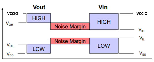
    As far as I knew that most of 3.3V CMOS MCU has VIH of 2V, and VOH is higher than VIH. VOH-VIH is the noise margin.

    For TMS570, VIH(min)=2V, VIL(max)=0.8V, VOH(min)=3V, and VOL(max)=0.2V

            The HIGH state noise margin is: VOH(min)-VIH(min) = 3V - 2V = 1V

            The LOW state noise margin  is: VIL(max) - VOL(max) = 0.8V - 0.2V = 0.6V

    What are the spec value of VIH and VIL of the HOST MCU?

  • Hi QJ Wang,

    The RM46L852 works as you have told me, but the micro-SDXC is more restrictive, from what I have read of the Physical layer specification of the SD Card, it recommends a value approx to 3.3V. However, it have checked this documents and I have verified that:

    Output Voltage:
    VDD=3.3V
    VOH: 0.75*VDD
    VOL: 0.125*VDD

    Input Voltage:
    VDD=3.3V
    VIH: 0.625*VDD
    VIL: 0.25 *VDD

    Best regards,

    Francisco