Part Number: TM4C1292NCPDT
I am writing some I2C master drivers for a custom PCB (TM4C1292NCPDTT3R) to talk to a smart battery of I2C/SMBus. I am utilizing TI's provided TivaWare SW API here.
I'm having a couple issues setting up the master drivers on I2C1SCL and I2C1SDA. The desired goal is to have a master that will query the battery for 2 bytes at a SCL of 100kHz max (per SMBus protocol). I am having some trouble setting the correct bus speed and reading the 2 bytes of data from the battery/slave.
Here is my initialization code:
GPIOPinConfigure(GPIO_PG0_I2C1SCL); // master SCL (battery slave)
GPIOPinConfigure(GPIO_PG1_I2C1SDA); // master SDA (battery slave)
GPIOPinTypeI2CSCL(GPIO_PORTG_BASE, GPIO_PIN_0); // configure master SCL line
GPIOPinTypeI2C(GPIO_PORTG_BASE, GPIO_PIN_1);    // configure master SDA line

SysCtlPeripheralEnable(SYSCTL_PERIPH_I2C1);
while(!SysCtlPeripheralReady(SYSCTL_PERIPH_I2C1));

I2CMasterInitExpClk(I2C1_BASE, SysCtlClockGet(), I2C_MASTER_SLOW_MODE); // slow mode = 100kbps transfers
I2CMasterTimeoutSet(I2C1_BASE, 0xDA0);
Here is the read implementation:
typedef enum
{
    I2C_MASTER_WRITE = 0,   // specifies that the master will be initiating write transactions
    I2C_MASTER_READ = 1,    // specifies that the master will be initiating read transactions
} boolI2CMasterMode_t;

void configNextMessage(boolI2CMasterMode_t msgMode)
{
    I2CMasterSlaveAddrSet(I2C1_BASE, BATTERY_ADDRESS, msgMode);
}

uint16_t readBatteryData(uint8_t readCommand)
{
    uint8_t highByte = 0u;
    uint8_t lowByte  = 0u;

    configNextMessage(I2C_MASTER_WRITE);
    I2CMasterDataPut(I2C1_BASE, readCommand);
    I2CMasterControl(I2C1_BASE, I2C_MASTER_CMD_SINGLE_SEND);
    while(I2CMasterBusy(I2C1_BASE))
    {
        // intentionally blank
    }


    configNextMessage(I2C_MASTER_READ);
//    I2CMasterBurstLengthSet(I2C1_BASE, 2);
    I2CMasterControl(I2C1_BASE, I2C_MASTER_CMD_SINGLE_RECEIVE);
    while(I2CMasterBusy(I2C1_BASE))
    {
        // intentionally blank
    }
    highByte = I2CMasterDataGet(I2C1_BASE);


    I2CMasterControl(I2C1_BASE, I2C_MASTER_CMD_SINGLE_RECEIVE);
    while(I2CMasterBusy(I2C1_BASE))
    {
        // intentionally blank
    }
    lowByte = I2CMasterDataGet(I2C1_BASE);


    return (highByte << 8) + lowByte;
}
Here is a scope capture of the digital signal with the analog equivalent:
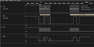
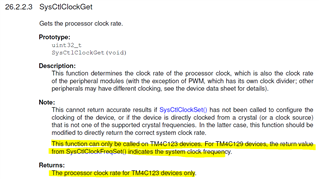
In the initialization, I pass I2CMasterInitExpClk(...) I pass I2C_MASTER_SLOW_MODE which is false. Per the API documentation, I would expect this to provide clock speeds of 100kbps; however, it looks like it is using the fast mode of 400kbps in this example. Any thoughts? When I pass true as that param, the device uses super fast mode of 1Mbps. I even try setting the MCLKOCNT register directly through the I2CMasterTimeoutSet function, but it doesn't seem to have an effect.
Judging by the looks of the analog lines, this definitely seems too fast for the slave (which is only rated for 100kbps). I believe part of my data acquisition issues are related to this clocking speed. Though I am not confident in how I am reading the 2 bytes back from the slave. Below is an image of the capture when I try to read the serial number from the slave.
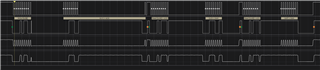
The first byte I get back, the 0x39, is correct; however, that 0xFF is not. Any recommendations on how to better utilize the API to poll 2 bytes?
Thank you