This thread has been locked.

If you have a related question, please click the "Ask a related question" button in the top right corner. The newly created question will be automatically linked to this question.

TM4C1292NCPDT: Offsetting PWM Generator Blocks by 180 Degrees

Part Number: TM4C1292NCPDT

We have a custom board using the TM4C1292NCPDT

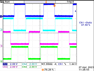
The board will be using two interleaved PWM signal pairs. Currently, I am running PWM Gen 0 and PWM Gen 1 in UP-DOWN mode. Is there a way to offset the generator blocks so they are 180 degrees out of phase using the TI SW API? For example, in the image below, I want L1 and L2 to be 180 degrees out of phase and H1 and H2 to be 180 degrees out of phase, while retaining the same duty cycles. Is there a way in the SW API to set the starting count of one of the generators to accomplish this? The duty cycle will change during runtime, so it needs to be a true, 180 degree phase shift (instead of inverting a 50% duty cycle signal).

Here is the corresponding init code:

#define GENERATOR_PERIOD_COUNTS 1000
#define DEAD_BAND_DURATION_COUNTS 50

SysCtlPeripheralEnable(SYSCTL_PERIPH_GPIOF);
while(!SysCtlPeripheralReady(SYSCTL_PERIPH_GPIOF));

// Configure the GPIO for PWM peripheral use.
GPIOPinConfigure(GPIO_PF0_M0PWM0);
GPIOPinConfigure(GPIO_PF1_M0PWM1);
GPIOPinConfigure(GPIO_PF2_M0PWM2);
GPIOPinConfigure(GPIO_PF3_M0PWM3);
GPIOPinTypePWM(GPIO_PORTF_BASE, GPIO_PIN_0);
GPIOPinTypePWM(GPIO_PORTF_BASE, GPIO_PIN_1);
GPIOPinTypePWM(GPIO_PORTF_BASE, GPIO_PIN_2);
GPIOPinTypePWM(GPIO_PORTF_BASE, GPIO_PIN_3);

SysCtlPeripheralEnable(SYSCTL_PERIPH_PWM0);         // enable the pwm peripheral
while(!SysCtlPeripheralReady(SYSCTL_PERIPH_PWM0));  // wait for the peripheral to be ready
PWMClockSet(PWM0_BASE, PWM_SYSCLK_DIV_1);           // Sets the PWM clock configuration to use the system clock with a divider of 1

/*
 * Configure generator blocks to run in up/down mode which allows
 * use of the built-in dead band time. In this mode, the synchronization of
 * the 2 signals in each generator are synchronized by default, so we
 * don't need to set any.
 */
PWMGenConfigure(PWM0_BASE, PWM_GEN_0, PWM_GEN_MODE_UP_DOWN | PWM_GEN_MODE_NO_SYNC);
PWMGenConfigure(PWM0_BASE, PWM_GEN_1, PWM_GEN_MODE_UP_DOWN | PWM_GEN_MODE_NO_SYNC);

/*
 * Set the PWM period. Configures the reference counter that counts in up/down mode.
 *
 * f = PWM_ref_clk / N ... where f is the desired frequency, N is the passed param,
 * and PWM_ref_clk is the reference clock.
 */
PWMGenPeriodSet(PWM0_BASE, PWM_GEN_0, GENERATOR_PERIOD_COUNTS);
PWMGenPeriodSet(PWM0_BASE, PWM_GEN_1, GENERATOR_PERIOD_COUNTS);

/*
 * Enables dead band generation with a configurable buffer on both the rising and falling
 * edge of the signals. Enabling this will automatically synchronize the signal pairs in
 * each of the generator blocks.
 */
PWMDeadBandEnable(PWM0_BASE, PWM_GEN_0, DEAD_BAND_DURATION_COUNTS, DEAD_BAND_DURATION_COUNTS);
PWMDeadBandEnable(PWM0_BASE, PWM_GEN_1, DEAD_BAND_DURATION_COUNTS, DEAD_BAND_DURATION_COUNTS);

PWMPulseWidthSet(PWM0_BASE, PWM_OUT_0, 550); // complement signal PWM_OUT_1 updates automatically
PWMPulseWidthSet(PWM0_BASE, PWM_OUT_2, 550); // complement signal PWM_OUT_3 updates automatically

PWMGenEnable(PWM0_BASE, PWM_GEN_0);
PWMGenEnable(PWM0_BASE, PWM_GEN_1);

PWMSyncTimeBase(PWM0_BASE, PWM_GEN_1_BIT | PWM_GEN_0_BIT);

PWMOutputState(PWM0_BASE, PWM_OUT_2_BIT | PWM_OUT_3_BIT | PWM_OUT_0_BIT | PWM_OUT_1_BIT, true);

  • Hi,

      You can invert L2 and H2 to make them 180 out of phase with L1 and H1. 

  • Wouldn't this swap the duty cycles too? So if the duty cycle for L1 is 40%, then the inverted duty cycle for L2 would be 60%. I want both to have a 40% duty, but L2 just needs to occur exactly half a period later.

  • As I play with the inversion function, it looks like it is offsetting the signals correctly; however, it's not accounting for the dead band correctly. It's almost as if I need to write in a negative deadband. The deadband that gets put in is actually added onto the rising and falling edges, instead of subtracted. So the best I can get is zero deadband, which is an issue. I need some guarantee those L2 and H2 will not ever be high at the same time. Is there a way to apply a negative deadband to the inverted signal?

  • Hi,

      I think you should be able to synchronize GEN0 with GEN1 and create the phase relationship between L1 and L2. 

    Synchronized. The PWM generator and its two outputs signals are used in conjunction with
    other PWM generators using a common, unified time base. If multiple PWM generators are
    configured with the same counter load value, synchronization can be used to guarantee that
    they also have the same count value (the PWM generators must be configured before they are
    synchronized). With this feature, more than two MnPWMn signals can be produced with a known
    relationship between the edges of those signals because the counters always have the same
    values. Other states in the module provide mechanisms to maintain the common time base and
    mutual synchronization.

  • Hi,

      Do you still need help on setting up 180 degree out of phase PWM? TivaWare API does not natively support this. You will have to get around the API to achieve this. I was able to get two pairs of dead-band signals and the two pairs are 180 out of phase with each other. See below. 


    I modify the stock example pwm_dead_band.c. 

    //*****************************************************************************
    //
    // pwm_dead_band.c - Example demonstrating the PWM dead-band generator.
    //
    // Copyright (c) 2019-2020 Texas Instruments Incorporated.  All rights reserved.
    // Software License Agreement
    // 
    // Texas Instruments (TI) is supplying this software for use solely and
    // exclusively on TI's microcontroller products. The software is owned by
    // TI and/or its suppliers, and is protected under applicable copyright
    // laws. You may not combine this software with "viral" open-source
    // software in order to form a larger program.
    // 
    // THIS SOFTWARE IS PROVIDED "AS IS" AND WITH ALL FAULTS.
    // NO WARRANTIES, WHETHER EXPRESS, IMPLIED OR STATUTORY, INCLUDING, BUT
    // NOT LIMITED TO, IMPLIED WARRANTIES OF MERCHANTABILITY AND FITNESS FOR
    // A PARTICULAR PURPOSE APPLY TO THIS SOFTWARE. TI SHALL NOT, UNDER ANY
    // CIRCUMSTANCES, BE LIABLE FOR SPECIAL, INCIDENTAL, OR CONSEQUENTIAL
    // DAMAGES, FOR ANY REASON WHATSOEVER.
    // 
    // This is part of revision 2.2.0.295 of the EK-TM4C1294XL Firmware Package.
    //
    //*****************************************************************************
    
    #include <stdbool.h>
    #include <stdint.h>
    #include "inc/hw_types.h"
    #include "inc/hw_memmap.h"
    #include "inc/hw_pwm.h"
    
    #include "driverlib/debug.h"
    #include "driverlib/gpio.h"
    #include "driverlib/pin_map.h"
    #include "driverlib/pwm.h"
    #include "driverlib/rom.h"
    #include "driverlib/rom_map.h"
    #include "driverlib/sysctl.h"
    #include "driverlib/uart.h"
    #include "utils/uartstdio.h"
    
    //*****************************************************************************
    //
    //! \addtogroup pwm_examples_list
    //! <h1>PWM Dead-band Generator Demo (pwm_dead_band)</h1>
    //!
    //! The example configures the PWM0 block to generate a 25% duty cycle signal
    //! on PF2 with dead-band generation.  This will produce a complement of PF2 on
    //! PF3 (75% duty cycle).  The dead-band generator is set to have a 10us delay
    //! on the rising and falling edges of the PF2 PWM signal.
    //!
    //! This example uses the following peripherals and I/O signals.
    //! - GPIO Port F peripheral (for PWM pins)
    //! - M0PWM2 - PF2
    //! - M0PWM3 - PF3
    //!
    //! UART0, connected to the Virtual Serial Port and running at 115,200, 8-N-1,
    //! is used to display messages from this application.
    //
    //*****************************************************************************
    
    //*****************************************************************************
    //
    // The variable g_ui32SysClock contains the system clock frequency in Hz.
    //
    //*****************************************************************************
    uint32_t g_ui32SysClock;
    
    //*****************************************************************************
    //
    // The error routine that is called if the driver library encounters an error.
    //
    //*****************************************************************************
    #ifdef DEBUG
    void
    __error__(char *pcFilename, uint32_t ui32Line)
    {
    }
    #endif
    
    //*****************************************************************************
    //
    // Configure the UART and its pins.  This must be called before UARTprintf().
    //
    //*****************************************************************************
    void
    ConfigureUART(void)
    {
        //
        // Enable the GPIO Peripheral used by the UART.
        //
        MAP_SysCtlPeripheralEnable(SYSCTL_PERIPH_GPIOA);
    
        //
        // Enable UART0.
        //
        MAP_SysCtlPeripheralEnable(SYSCTL_PERIPH_UART0);
    
        //
        // Configure GPIO Pins for UART mode.
        //
        MAP_GPIOPinConfigure(GPIO_PA0_U0RX);
        MAP_GPIOPinConfigure(GPIO_PA1_U0TX);
        MAP_GPIOPinTypeUART(GPIO_PORTA_BASE, GPIO_PIN_0 | GPIO_PIN_1);
    
        //
        // Initialize the UART for console I/O.
        //
        UARTStdioConfig(0, 115200, g_ui32SysClock);
    }
    
    //*****************************************************************************
    //
    // Configure PWM for dead-band generation.
    //
    //*****************************************************************************
    
    #define PWM1GENA_OFFSET 0xA0
    #define PWM2GENA_OFFSET 0xE0
    #define PWM1GENB_OFFSET 0xA4
    #define PWM2GENB_OFFSET 0xE4
    #define PWM1CMPA_OFFSET 0x98
    #define PWM1CMPB_OFFSET 0x9C
    #define PWM2CMPA_OFFSET 0xD8
    #define PWM2CMPB_OFFSET 0xDC
    
    int
    main(void)
    {
        uint32_t ui32PWMClockRate;
    
        //
        // Run from the PLL at 120 MHz.
        // Note: SYSCTL_CFG_VCO_240 is a new setting provided in TivaWare 2.2.x and
        // later to better reflect the actual VCO speed due to SYSCTL#22.
        //
        g_ui32SysClock = MAP_SysCtlClockFreqSet((SYSCTL_XTAL_25MHZ |
                                                 SYSCTL_OSC_MAIN |
                                                 SYSCTL_USE_PLL |
                                                 SYSCTL_CFG_VCO_240), 120000000);
    
        //
        // Initialize the UART.
        //
        ConfigureUART();
    
        //
        // Display the setup on the console.
        //
        UARTprintf("PWM ->\n");
        UARTprintf("  Module: PWM0\n");
        UARTprintf("  Pin(s): PF2 and PF3\n");
        UARTprintf("  Features: Dead-band Generation\n");
        UARTprintf("  Duty Cycle: 25%% on PF2 and 75%% on PF3\n");
        UARTprintf("  Dead-band Length: 250 cycles\n\n");
    
        //
        // Enable the GPIO port that is used for the on-board LED.
        //
        MAP_SysCtlPeripheralEnable(SYSCTL_PERIPH_GPION);
    
        //
        // Enable the GPIO pin for the LED (PN0) as an output.
        //
        MAP_GPIOPinTypeGPIOOutput(GPIO_PORTN_BASE, GPIO_PIN_0);
    
        //
        // The PWM peripheral must be enabled for use.
        //
        MAP_SysCtlPeripheralEnable(SYSCTL_PERIPH_PWM0);
    
        //
        // Enable the GPIO port that is used for the PWM output.
        //
        MAP_SysCtlPeripheralEnable(SYSCTL_PERIPH_GPIOF);
    
        //
        // Enable the GPIO port that is used for the PWM output.
        //
        MAP_SysCtlPeripheralEnable(SYSCTL_PERIPH_GPIOG);
    
    
        //
        // Configure the GPIO pad for PWM function on pins PF2 and PF3.
        //
        MAP_GPIOPinConfigure(GPIO_PF2_M0PWM2);
        MAP_GPIOPinConfigure(GPIO_PF3_M0PWM3);
        MAP_GPIOPinTypePWM(GPIO_PORTF_BASE, GPIO_PIN_2);
        MAP_GPIOPinTypePWM(GPIO_PORTF_BASE, GPIO_PIN_3);
    
        //
        // Configure the GPIO pad for PWM function on pins PF2 and PF3.
        //
        MAP_GPIOPinConfigure(GPIO_PG0_M0PWM4);
        MAP_GPIOPinConfigure(GPIO_PG1_M0PWM5);
        MAP_GPIOPinTypePWM(GPIO_PORTG_BASE, GPIO_PIN_0);
        MAP_GPIOPinTypePWM(GPIO_PORTG_BASE, GPIO_PIN_1);
    
        //
        // Set the PWM clock to be SysClk / 8.
        //
        MAP_PWMClockSet(PWM0_BASE, PWM_SYSCLK_DIV_8);
    
        //
        // Use a local variable to store the PWM clock rate which will be
        // 120 MHz / 8 = 15 MHz. This variable will be used to set the
        // PWM generator period.
        //
        ui32PWMClockRate = g_ui32SysClock / 8;
    
        //
        // Configure PWM2 to count up/down with synchronization.
    
        MAP_PWMGenConfigure(PWM0_BASE, PWM_GEN_1,
                            PWM_GEN_MODE_UP_DOWN | PWM_GEN_MODE_SYNC);
    
        MAP_PWMGenConfigure(PWM0_BASE, PWM_GEN_2,
                            PWM_GEN_MODE_UP_DOWN | PWM_GEN_MODE_SYNC);
    
        // For PWM1GENA, set pin high when counter is zero and reset pin to low
        // when CMPA is matched during count up.
    
        HWREG(PWM0_BASE + PWM1GENA_OFFSET) = 0x0;
        HWREG(PWM0_BASE + PWM1GENA_OFFSET) = 0x023;
    
        // For PWM2GENA, set pin high when counter is reloaded and reset pin to low
        // when CMPA is matched during count down.
    
        HWREG(PWM0_BASE + PWM2GENA_OFFSET) = 0x0;
        HWREG(PWM0_BASE + PWM2GENA_OFFSET) = 0x4C;
    
        //
        // Set the PWM period to 250Hz.  To calculate the appropriate parameter
        // use the following equation: N = (1 / f) * PWMClk.  Where N is the
        // function parameter, f is the desired frequency, and PWMClk is the
        // PWM clock frequency based on the system clock.
        //
        MAP_PWMGenPeriodSet(PWM0_BASE, PWM_GEN_1, (ui32PWMClockRate / 250));
    
        MAP_PWMGenPeriodSet(PWM0_BASE, PWM_GEN_2, (ui32PWMClockRate / 250));
    
        //
        // Set PWM1 CMPA to 40% of half period during count up
        // Set PWM2 CMPA to 10% of half period during count down
        //
    
        HWREG(PWM0_BASE + PWM1CMPA_OFFSET) = MAP_PWMGenPeriodGet(PWM0_BASE, PWM_GEN_1) * 0.4;
        HWREG(PWM0_BASE + PWM2CMPA_OFFSET) = MAP_PWMGenPeriodGet(PWM0_BASE, PWM_GEN_2) * 0.1;
    
        PWMSyncUpdate(PWM0_BASE, PWM_GEN_1_BIT | PWM_GEN_2_BIT);
        //
        // Enable the dead-band generation on the PWM0 output signal.
        // These signals will have a 100us gap between the
        // rising and falling edges.
        // For this example the PWM clock rate is 15 MHz, so we will use
        // 150 cycles (1500 cycles / 15MHz = 100us) on both the rising and falling
        // edges of PF2.  Reference the datasheet for more information on PWM
        // dead-band generation.
        //
        MAP_PWMDeadBandEnable(PWM0_BASE, PWM_GEN_1, 1500, 1500);
        MAP_PWMDeadBandEnable(PWM0_BASE, PWM_GEN_2, 1500, 1500);
    
        //
        // Enable the PWM Out Bit 2 (PF2) and Bit 3 (PF3) output signals.
        //
        MAP_PWMOutputState(PWM0_BASE, PWM_OUT_2_BIT | PWM_OUT_3_BIT, true);
        MAP_PWMOutputState(PWM0_BASE, PWM_OUT_4_BIT | PWM_OUT_5_BIT, true);
    
        //
        // Enable the PWM generator block.
        //
        MAP_PWMGenEnable(PWM0_BASE, PWM_GEN_1);
        MAP_PWMGenEnable(PWM0_BASE, PWM_GEN_2);
    
    
        //
        // Loop forever blinking an LED while the PWM signals are generated.
        //
        while(1)
        {
            //
            // Turn on the LED.
            //
            MAP_GPIOPinWrite(GPIO_PORTN_BASE, GPIO_PIN_0, GPIO_PIN_0);
    
            //
            // This function provides a means of generating a constant length
            // delay.  The function delay (in cycles) = 3 * parameter.  Delay
            // 0.5 seconds arbitrarily.
            //
            MAP_SysCtlDelay((g_ui32SysClock / 2) / 3);
    
            //
            // Turn off the LED.
            //
            MAP_GPIOPinWrite(GPIO_PORTN_BASE, GPIO_PIN_0, 0x00);
    
            //
            // This function provides a means of generating a constant length
            // delay.  The function delay (in cycles) = 3 * parameter.  Delay
            // 0.5 seconds arbitrarily.
            //
            MAP_SysCtlDelay((g_ui32SysClock / 2) / 3);
        }
    }