This thread has been locked.

If you have a related question, please click the "Ask a related question" button in the top right corner. The newly created question will be automatically linked to this question.

MSPM0G3507: UART DMA interrupt issue

Part Number: MSPM0G3507

Hi,

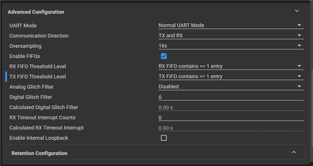
I am exploring MSP-M0G3607 MCU. I am using CCS Theia 0.9 with SDK 0.58. I need to dump a bunch of data on the serial console. To do this,  I am using the "uart_tx_console_multibyte_fifo_dma" example. I have observed the issue in the UART DMA interrupt. I have configured UART as shown in the below image.

After a specific amount of data was dumped on the serial console, I could not get a DMA interrupt as shown in the below image.

Am I missing something here? Please guide me.

Thanks and Regrads,

Virendra Dalal

Einfochips 

  • Hi Virendra,

    Within the MySecureSoftware folder you downloaded the SDK from there is a document which includes the Errata and enhancements between early and production samples. Look for the "Early Samples Functional Differences Document"

    This sounds like the UART_05 issue from that document. 

    Can you add the following below where you set your gConsoleTxDMATransmitted flag in your UART Handler? 

    DEBUG_UART_INST->INT_EVENT2.IMASK = UART_INT_EVENT2_IMASK_TXINT_CLR;

    In the past I've found that this really has to be done within that DMADONE Interrupt as described in the workaround. This workaround will not be needed on production devices.

    Best Regards,
    Brandon Fisher

  • Hi Brandon,

    Thank you for your quick response.

    As you have mentioned, I have updated the handler as you can see in the below image.

    However, after adding this caused a DMA interrupt stuck in the very first UART transaction as I have shown in the below image.

    Also, I do not know if it is related, but in my application, I have also configured ADC, PWM, and SysTick interrupts. Is any of these interrupts can cause problems in UART DMA ?

    Kindly help me out on this.

    Regards,

    Virendra Dalal

    Einfochips

  • Hi Virendra,

    Please also comment out the call to: DL_UART_disableDMATransmitEvent(DEBUG_UART_INST); 

    We are effectively moving this portion of the workaround to the interrupt handler so it occurs quickly without being preempted, so you should comment it out here. 

    Also, I do not know if it is related, but in my application, I have also configured ADC, PWM, and SysTick interrupts. Is any of these interrupts can cause problems in UART DMA ?

    Its possible, are you using the DMA in conjunction with any of these peripherals? That would be the first place I'd look. 

    Best Regards,
    Brandon Fisher

  • Hi Brandon,

    Thank you for the quick response.

    I have tried commenting out "DL_UART_disableDMATransmitEvent(DEBUG_UART_INST); ". But, the issue remains the same.

    Also, I do not know if it is related, but in my application, I have also configured ADC, PWM, and SysTick interrupts. Is any of these interrupts can cause problems in UART DMA ?

    Its possible, are you using the DMA in conjunction with any of these peripherals? That would be the first place I'd look. 

    No, I am not using DMA in conjunction with any of the peripherals.

    For your reference, I am attaching screenshots for the UART configuration in syscfg file.


    Regards,

    Virendra Dalal

    Einfochips

  • Hi Virendra,

    I don't see anything obviously wrong here. Have you changed anything else from the example about UART like the Baud rate or clock settings?

    In my setup the example is running just fine with this configuration.

    Does the UART fail at a consistent place each time or does it seem to be random? 

    Best Regards,
    Brandon Fisher

  • Hi Brandon,

    Have you changed anything else from the example about UART like the Baud rate or clock settings?

    No, I have exact same configurations as the UART DMA example. An example project is running fine, but my firmware application is not working.  

    Does the UART fail at a consistent place each time or does it seem to be random? 

    Yes, it does fail at the same place. My firmware application basically first initializes all the peripherals and then waits for the button interrupt. I printed a welcome message on UART after initialization is done, and that works fine. But when I get the button interrupt, I start taking ADC samples and print these samples over UART. On this first sample print, it always gets stuck.

    I have also tried changing the FIFO levels as shown in the below snapshot.


    I have also tried the same configuration as suggested in the "MSPM0_EarlySamplesFunctionalDifferences_v1p0" document.

    Is there any other UART configuration that I am missing? Or can you suggest any other way?

    Thanks and Regards,

    Virendra Dalal

    Einfochips

  • Hi Virendra,

    When you start capturing ADC samples, how are you then printing the message out to UART? 

    I think there may be a hint in how the ADC is triggering the UART since the failure occurs here. 

    Do you call the UART_console_write function from inside your ADC done ISR? What does this structure look like? 

    Best Regards,
    Brandon Fisher

  • Hi Brandon,

    When you start capturing ADC samples, how are you then printing the message out to UART? 

    I think there may be a hint in how the ADC is triggering the UART since the failure occurs here. 

    Do you call the UART_console_write function from inside your ADC done ISR? What does this structure look like?

    Yes, you are right. I mistakenly printed one line in ADC ISR. I can now print all the ADC samples without any issues.

    Thanks for your continuous support.

    I do have one doubt regarding the PWM APIs. I have configured PWM0 for two channels as you can see in the below image:

    Is there any way to stop one PWM channel? I have tried to set the first PWM channel capture compare value to 0, but does not seem to work. I need to use the "DL_TimerG_stopCounter" method, which stops the whole PWM group. 

    Can you suggest me any way of doing this?

    Thanks and Regards,
    Virendra Dalal

    Einfochips

  • Hi Virendra,

    Yes, you are right. I mistakenly printed one line in ADC ISR. I can now print all the ADC samples without any issues.

    Thanks for your continuous support.

    Great, glad to hear the UART output is working now.

    Is there any way to stop one PWM channel? I have tried to set the first PWM channel capture compare value to 0, but does not seem to work. I need to use the "DL_TimerG_stopCounter" method, which stops the whole PWM group. 

    Are you wanting the PWM pin to go low or high when idle/disconnected?

    You should be able to set the duty cycle to 0%, by setting your CCP value to the load value. 

    Alternatively, and I should note that I haven't actually tried this method before, you could also disconnect the TIMx channel from the relevant pin using the IOMUX. In that mode it could be left as high z or reconnected as a GPIO and driven whichever way you want.

    Best Regards,
    Brandon Fisher

  • Hi Brandon,

    I did manage to stop the individual PWM channel. I can correctly run both of the PWM channels independently. The issue was I have set the Max CCP value to 16000 which is basically a 0% duty cycle. In order to get it to work, I need to set this value to 15999. 

    Thank you for your all efforts and support.

    Thanks and Regards,

    Virendra Dalal

    Einfochips