This thread has been locked.

If you have a related question, please click the "Ask a related question" button in the top right corner. The newly created question will be automatically linked to this question.

TMS570LC4357: Confused by Halcogen generated adcGetData (calculated count from GxINTCR)

Part Number: TMS570LC4357
Other Parts Discussed in Thread: HALCOGEN

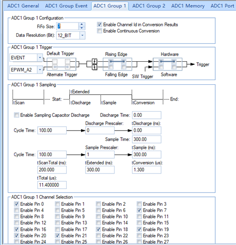
I'm using ADC triggered from PWM SOCA, not in Continuous Conversion mode.

I got HALCoGen setup here
generated code like this

uint32 adcGetData(adcBASE_t *adc, uint32 group, adcData_t * data)
{
    uint32  i;
    uint32  buf;
    uint32  mode;    
    uint32  index = (adc == adcREG1) ? 0U : 1U;
	
	uint32  intcr_reg = adc->GxINTCR[group];
    uint32  count = (intcr_reg >= 256U) ? s_adcFiFoSize[index][group] : (s_adcFiFoSize[index][group] - (uint32)(intcr_reg & 0xFFU));
    adcData_t *ptr = data; 

/* USER CODE BEGIN (16) */
/* USER CODE END */

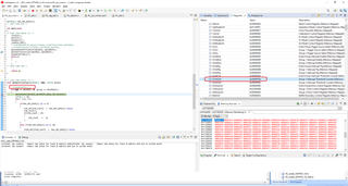
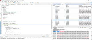
During code execution, I got somewhere count is actual negative results:

So why is this? is it a bug or I should just access ADC results directly from ADC buffer instead?

thanks

  • Hi Hongbo,

    We started working on your issue and will provide an update soon.

    --

    Thanks & regards,
    Jagadish.

  • Hi Hongbo,

    During code execution, I got somewhere count is actual negative results:

    The "count" variable is declared as uint32(unsigned int), then how you got negative value for count?

    --

    Thanks & regards,
    Jagadish.

  • Did you see the count result? 4294967119 which is computed as 7 - 184 -> uint32_t

  • Hi Hongbo,

    Apologies for the delay in the update.

    After debugging i understood it might be a debug issue.

    Actually, if we set any breakpoints "adcNotification" and "adcGetData" functions you can see that count value as negative. This is because ETPWM will not stop even after we pause debugging using breakpoints, the PWM will get generate even though it hits the breakpoint and it will again trigger the ADC for conversion. In your case you will set "GxINTCR" value to the 7 before conversion start right so if the number of conversions are more than 7 then the register value will be decremented to less than zero.

    For example:

    I just selected 3 channels in this example and i commented out the stopping PWM signal 

    The initial value of GxINTCR in my example is 16 and now you can see that GxINTCR value becomes 0xFFD0.

    Now i am just stopping PWM signal and want to see the GxINTCR value:

    Now you can see that, i just initialized GxINTCR with 0x10 and GxINTCR was stopped at 0x0D that means exactly after 3 conversions. So in this case if i debug further i can see the count value as 3.

    I can also explain why i got oxFFD0 in the first case, it is because actually i initialized Group-1 with 64 buffers, so the overflow will occurs after 64 conversions, so the ADC will start convert upto 64 conversions.

    As i initialized GxINTCR with 0x10 right so after 16 conversions this register value will become 0 and if ADC did next conversion then this register value becomes -1 which means 0xFFFF, and for next conversion this register value becomes 0xFFFE which means -2 and this process will continue till -48(total 64 conversions) which means  0xFFD0.

    I hope this will clarify your doubts.

    --

    Thanks & regards,
    Jagadish.