Hello all. I solicit your expertise.
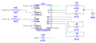
I have used the TM4C123GH6 series for many years but am now running up against a problem I cannot yet resolve. Most of my projects are stand-alone or just use the UART for debugging purposes to another computer with UART pins. This is the first project requiring use of a serial (RS232) interface to the microcontroller's UART pins (UART0 in this case). I am using a TI TRS3232EIDW chip as the interface. The issue is that when I have the board connected to the PC (Sabrent USB to RS232 converter) and the XDS100 debug interface is connected, I get a serial output that I expect but when the XDS100 is removed, the serial connection ceases to function and the board becomes recoverable. Connection of the XDS100 again does NOT restore serial communications and resetting the board (reset button connecting GND to RST pin) does nothing; a power cycle does nothing. The only way to get anything to run again is to re-flash the board with the XDS100.
I have used the TM4C123GH6 for some time and have never experienced this issue before, so I feel it is related to the use of the serial interface. I did check all solder joints and I cannot see any issues but I did reflow the UART and ground pins to be sure. I checked the difference between my power supply and the RS232 interface ground (pin 5) and it's steady at about 1mV. I checked the 3.3V rail when the XDS100 is removed and see less than a 10mV (3.31 to 3.30) change. There are other components connected to the microcontroller (FRAM and a sensor each over different SSI interfaces) but these parts have been used in many projects with no issues; I do not suspect them to be the issue here.
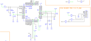
Segments of the schematic are below. I have left out the FRAM and sensor portions as I do not think they are causing this issue.


U6 is a "RICOH, R1524H033B-T1-FE VOLTAGE REGULATOR, LINEAR, 3.3V, 200MA"
As a test, I modified the TI uart_echo.c program in CCS to just monitor the UART and return the character it receives and it works as expected so long as both the serial cable and the XDS100 are connected. But, this program has the same issue when the XDS100 is removed from the circuit. No reset or power cycle will recover the functionality. A re-flash is required. I did try adding a delay (~1 second) on line 102 to see if that would make any difference in the startup. It did not. The content of that program:
//*****************************************************************************
//
// uart_echo.c - Example for reading data from and writing data to the UART in
//               an interrupt driven fashion.
//
// Copyright (c) 2011-2014 Texas Instruments Incorporated.  All rights reserved.
// Software License Agreement
//
// Texas Instruments (TI) is supplying this software for use solely and
// exclusively on TI's microcontroller products. The software is owned by
// TI and/or its suppliers, and is protected under applicable copyright
// laws. You may not combine this software with "viral" open-source
// software in order to form a larger program.
//
// THIS SOFTWARE IS PROVIDED "AS IS" AND WITH ALL FAULTS.
// NO WARRANTIES, WHETHER EXPRESS, IMPLIED OR STATUTORY, INCLUDING, BUT
// NOT LIMITED TO, IMPLIED WARRANTIES OF MERCHANTABILITY AND FITNESS FOR
// A PARTICULAR PURPOSE APPLY TO THIS SOFTWARE. TI SHALL NOT, UNDER ANY
// CIRCUMSTANCES, BE LIABLE FOR SPECIAL, INCIDENTAL, OR CONSEQUENTIAL
// DAMAGES, FOR ANY REASON WHATSOEVER.
//
// This is part of revision 2.1.0.12573 of the EK-LM4F232 Firmware Package.
//
//*****************************************************************************

#include <stdint.h>
#include <stdbool.h>
#include <stdio.h>
#include <stdlib.h>
#include "inc/hw_types.h"
#include "inc/hw_memmap.h"
#include "inc/hw_gpio.h"
#include "inc/hw_ssi.h"
#include "inc/tm4c123gh6pm.h"
#include "driverlib/debug.h"
#include "driverlib/fpu.h"
#include "driverlib/ssi.h"
#include "driverlib/gpio.h"
#include "driverlib/interrupt.h"
#include "driverlib/pin_map.h"
#include "driverlib/sysctl.h"
#include "driverlib/adc.h"
#include "driverlib/timer.h"
#include "driverlib/rom.h"
#include "inc/hw_ints.h"
#include "driverlib/uart.h"
#include "utils/uart1_stdio.h"
//#include "grlib/grlib.h"

//*****************************************************************************
//
//! \addtogroup example_list
//! <h1>UART Echo (uart_echo)</h1>
//!
//! This example application utilizes the UART to echo text.  The first UART
//! (connected to the USB debug virtual serial port on the evaluation board)
//! will be configured in 115,200 baud, 8-n-1 mode.  All characters received on
//! the UART are transmitted back to the UART.
//
//*****************************************************************************
#define UART_DEBUG 0

unsigned char Str[72];
//*****************************************************************************
//
// The error routine that is called if the driver library encounters an error.
//
//*****************************************************************************
#ifdef DEBUG
void
__error__(char *pcFilename, uint32_t ui32Line)
{
}
#endif

//*****************************************************************************
//
// The UART interrupt handler.
//
//*****************************************************************************
void UARTIntHandler(void) {
    uint32_t ui32Status;
    ui32Status = ROM_UARTIntStatus(UART0_BASE, true);
    ROM_UARTIntClear(UART0_BASE, ui32Status);
    char c[] = ROM_UARTCharGetNonBlocking(UART0_BASE);
    while(ROM_UARTCharsAvail(UART0_BASE)){}
	UARTprintf(UART_DEBUG, "Received: %c\n", *c);
	if (c[0] == 's') {UARTprintf(UART_DEBUG, "   --> SAMPLE\n");}
}

//*****************************************************************************
//
// This example demonstrates how to send a string of data to the UART.
//
//*****************************************************************************
int
main(void)
{
    ROM_FPULazyStackingEnable();
    ROM_SysCtlClockSet(SYSCTL_SYSDIV_1 | SYSCTL_USE_OSC | SYSCTL_OSC_MAIN |
                       SYSCTL_XTAL_16MHZ);
    ROM_SysCtlDelay(22222222);
    // Enable GPIOA
    ROM_SysCtlPeripheralEnable(SYSCTL_PERIPH_GPIOA);
    while(!ROM_SysCtlPeripheralReady(SYSCTL_PERIPH_GPIOA))
		{
		}
    ROM_SysCtlPeripheralEnable(SYSCTL_PERIPH_UART0);
   	// Enable UART0
    	while(!ROM_SysCtlPeripheralReady(SYSCTL_PERIPH_UART0))
    	{
    	}
    ROM_IntMasterEnable();
    ROM_GPIOPinTypeUART(GPIO_PORTA_BASE, GPIO_PIN_0 | GPIO_PIN_1);
    ROM_UARTConfigSetExpClk(UART0_BASE, ROM_SysCtlClockGet(), 115200,
                            (UART_CONFIG_WLEN_8 | UART_CONFIG_STOP_ONE |
                             UART_CONFIG_PAR_NONE));

  	//ROM_GPIOPadConfigSet(GPIO_PORTA_BASE, GPIO_PIN_0, GPIO_STRENGTH_4MA, GPIO_PIN_TYPE_STD_WPU);
    //	ROM_GPIOPadConfigSet(GPIO_PORTA_BASE, GPIO_PIN_1, GPIO_STRENGTH_4MA, GPIO_PIN_TYPE_STD_WPD);


    IntRegister(INT_UART0, UARTIntHandler);
    ROM_IntEnable(INT_UART0);
    ROM_UARTIntEnable(UART0_BASE, UART_INT_RX | UART_INT_RT);
    UARTprintf(UART_DEBUG, "Testing\n");

    while(1)
    {
    }
}
In summary I have tried:
* While maintaining the serial connection, I remove the XDS100. The system appears to cease operating at the moment of disconnection.
* Re-connection of the XDS100 does not restore serial communications.
* While maintaining the XDS100, I can remove the serial cable at the DB9 and reconnect it and the system continues to operate.
* Removal of the XDS100, serial cable, and power and then reconnecting them in any order (I've tried them all) does not matter. The system is not recoverable without re-flashing the microcontroller.
* I added a 10k pull-up to PA0 (UART0Rx) and that made no difference either.
Unfortunately this board has no LED indicators besides power, so I cannot yet determine if the system is running after a reset. I'll be adding an LED to one of the pins and have it pulse once a second or so as some indication of it running. This will also let me check if the system runs upon a re-flash with no serial cable connected; right now my only indication is the serial output.
Any thoughts on what might be going on and what I can try next?

