This thread has been locked.

If you have a related question, please click the "Ask a related question" button in the top right corner. The newly created question will be automatically linked to this question.

MSP432E401Y: How to execute code from external SDRAM.

Part Number: MSP432E401Y
Other Parts Discussed in Thread: TMS570LC4357,

Dear TI Team,

 1.  I am try to execute code from SDRAM by changing the Linker script file as suggest in below thread.

https://e2e.ti.com/support/microcontrollers/arm-based-microcontrollers-group/arm-based-microcontrollers/f/arm-based-microcontrollers-forum/1166516/msp43.

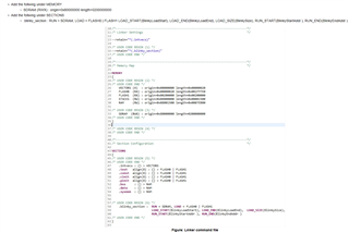
my current modified script file is as follows:

/*****************************************************************************/
/* Suppress warnings and errors: */
/* #10199-D CRC table operator (crc_table_for_<>) ignored:
CRC table operator cannot be associated with empty output section */
--diag_suppress=10199

--retain=interruptVectors

#define APP_BASE 0x60000000


#define RAM_BASE 0x60100000

MEMORY
{
FLASH (RX) : origin = APP_BASE, length = 0x00100000
SRAM (RWX) : origin = RAM_BASE, length = 0x00040000
}

/* The following command line options are set as part of the CCS project. */
/* If you are building using the command line, or for some reason want to */
/* define them here, you can uncomment and modify these lines as needed. */
/* If you are using CCS for building, it is probably better to make any such */
/* modifications in your CCS project and leave this file alone. */
/* */
/* --heap_size=0 */
/* --stack_size=256 */
/* --library=rtsv7M4_T_le_eabi.lib */

/* Section allocation in memory */

SECTIONS
{
#ifndef gen_crc_table
.intvecs: > APP_BASE
.text : > FLASH
.const : > FLASH
.cinit : > FLASH
.pinit : > FLASH
.rodata : > FLASH
.init_array : > FLASH
#else
.intvecs: > 0x00000000, crc_table(crc_table_for_intvecs)
.text : > FLASH, crc_table(crc_table_for_text)
.const : > FLASH, crc_table(crc_table_for_const)
.cinit : > FLASH, crc_table(crc_table_for_cinit)
.pinit : > FLASH, crc_table(crc_table_for_pinit)
.rodata : > FLASH, crc_table(crc_table_for_pinit)
.init_array : > FLASH, crc_table(crc_table_for_init_array)
.TI.crctab : > FLASH
#endif

.vtable : > RAM_BASE
.data : > SRAM
.bss : > SRAM
.sysmem : > SRAM
.stack : > SRAM
}

__STACK_TOP = __stack + 512;

/****************************************************************************************/


1. After copying .out file data into SDRAM i am calling below function. 

/****************************************************************************************/

UINT32 entryPiont;

entryPiont = 0x60000000; //SDRAM memory Address

appEntry = (void (*)(void))entryPiont;

(*appEntry)();

/**************************************************************************************/

2. The code is not executing from SDRAM as expected.

3. is there any modification need to be done in linker script or above function ?

Regards,

Naga Narasimha Rao P

  • Hi,

      Below is an example for a different MCU TMS570LC4357 that runs code out of SDRAM. This is to illustrate how the linker command file is setup the load address using LOAD_START, LOAD_END and the run address using RUN_START and RUN_END. The idea is to load the code to flash and then run the code from SDRAM. You will need to copy the code from flash to SDRAM before you can run from it. You need to also make sure that before you copy the code from flash to SDRAM, the SDRAM is fully initialized. I strongly suggest you start with a simple example first such as hello or blinky. Once you can run code like blinky out of SDRAM then you can adapt to a larger application. 

      Please note that for this device TMS570LC4357 the SDRAM is mapped to 0x80000000 while SDRAM for TM4C129 is mapped to 0x60000000. 

    /* Include Files */
    
    #include "HL_sys_common.h"
    #include "HL_system.h"
    
    /* USER CODE BEGIN (1) */
    #include "HL_emif.h"
    #include "HL_sys_mpu.h"
    #include "HL_gio.h"
    #include "HL_het.h"
    #include "HL_mibspi.h"
    /* USER CODE END */
    
    /** @fn void main(void)
    *   @brief Application main function
    *   @note This function is empty by default.
    *
    *   This function is called after startup.
    *   The user can use this function to implement the application.
    */
    
    /* USER CODE BEGIN (2) */
    #pragma SET_CODE_SECTION(".blinky_section")
    void blinky()
    {
    	int i;
    	gioSetDirection(hetPORT1, 1);
    	while(1)
    	{
    		gioToggleBit(hetPORT1, 0);
    		for(i=0;i<1000000;i++);
    	}
    }
    #pragma SET_CODE_SECTION()
    
    extern uint32 BlinkyLoadStart;
    extern uint32 BlinkyLoadEnd;
    extern uint32 BlinkySize;
    extern uint32 BlinkyStartAddr;
    extern uint32 BlinkyEndAddr;
    /* USER CODE END */
    
    uint8	emacAddress[6U] = 	{0xFFU, 0xFFU, 0xFFU, 0xFFU, 0xFFU, 0xFFU};
    uint32 	emacPhyAddress	=	1U;
    
    void main(void)
    {
    /* USER CODE BEGIN (3) */
    	int i;
        uint32 size=(uint32)&BlinkySize;
    
    	emif_SDRAMInit();
    
        for(i=0;i<size;i++)
        {
            ((char *)&BlinkyStartAddr)[i] =((char *)&BlinkyLoadStart)[i];
        }
    
    	blinky();
    	while(1);
    /* USER CODE END */
    }

    For details about the load and run addresses, you should go through ARM Assembly User's Guide https://www.ti.com/lit/pdf/spnu118

  • Dear Charles Tsai.

    I am writing .out file data into SDRAM using  custom application code which is running in internal flash memory using JTAG. which is going to receive data form ethernet interface using (QT GUI) application and the received data written in SDRAM from starting address. after that giving control to SDRAM starting address as mentioned above. 

    1. As you told before i did changes in  the linker script file memory map section. but now what you have given example is code is totally different.

    2. I want to run below example in SDRAM by writing the .out file into SDRAM  then start execution of code from SDRAM?

    3. what are the changes need to be done in below code and linker script?

    4. MSP432E401Y SDRAM start Address is 0X60000000 and the size of SDRAM in our custom boar is 512 Mega bits.

    5. what are the changes need to done in below example code and linker script file ?

    //*****************************************************************************
    //
    // blinky.c - Simple example to blink the on-board LED.
    //
    // Copyright (c) 2013-2017 Texas Instruments Incorporated.  All rights reserved.
    // Software License Agreement
    //
    // Texas Instruments (TI) is supplying this software for use solely and
    // exclusively on TI's microcontroller products. The software is owned by
    // TI and/or its suppliers, and is protected under applicable copyright
    // laws. You may not combine this software with "viral" open-source
    // software in order to form a larger program.
    //
    // THIS SOFTWARE IS PROVIDED "AS IS" AND WITH ALL FAULTS.
    // NO WARRANTIES, WHETHER EXPRESS, IMPLIED OR STATUTORY, INCLUDING, BUT
    // NOT LIMITED TO, IMPLIED WARRANTIES OF MERCHANTABILITY AND FITNESS FOR
    // A PARTICULAR PURPOSE APPLY TO THIS SOFTWARE. TI SHALL NOT, UNDER ANY
    // CIRCUMSTANCES, BE LIABLE FOR SPECIAL, INCIDENTAL, OR CONSEQUENTIAL
    // DAMAGES, FOR ANY REASON WHATSOEVER.
    //
    //*****************************************************************************
    
    #include <stdint.h>
    #include <stdbool.h>
    #include "ti/devices/msp432e4/driverlib/driverlib.h"
    
    //*****************************************************************************
    //
    //! \addtogroup example_list
    //! <h1>Blinky (blinky)</h1>
    //!
    //! A very simple example that blinks the on-board LED using direct register
    //! access.
    //
    //*****************************************************************************
    
    //*****************************************************************************
    //
    // The error routine that is called if the driver library encounters an error.
    //
    //*****************************************************************************
    #ifdef DEBUG
    void
    __error__(char *pcFilename, uint32_t ui32Line)
    {
        while(1);
    }
    #endif
    
    //*****************************************************************************
    //
    // Blink the on-board LED.
    //
    //*****************************************************************************
    int
    main(void)
    {
        volatile uint32_t ui32Loop;
    
        //
        // Enable the GPIO port that is used for the on-board LED.
        //
        SysCtlPeripheralEnable(SYSCTL_PERIPH_GPION);
    
        //
        // Check if the peripheral access is enabled.
        //
        while(!SysCtlPeripheralReady(SYSCTL_PERIPH_GPION))
        {
        }
    
        //
        // Enable the GPIO pin for the LED (PN0).  Set the direction as output, and
        // enable the GPIO pin for digital function.
        //
        GPIOPinTypeGPIOOutput(GPIO_PORTN_BASE, GPIO_PIN_0);
    
        //
        // Loop forever.
        //
        while(1)
        {
            //
            // Turn on the LED.
            //
            GPIOPinWrite(GPIO_PORTN_BASE, GPIO_PIN_0, GPIO_PIN_0);
    
            //
            // Delay for a bit.
            //
            for(ui32Loop = 0; ui32Loop < 200000; ui32Loop++)
            {
            }
    
            //
            // Turn off the LED.
            //
            GPIOPinWrite(GPIO_PORTN_BASE, GPIO_PIN_0, 0x0);
    
            //
            // Delay for a bit.
            //
            for(ui32Loop = 0; ui32Loop < 200000; ui32Loop++)
            {
            }
        }
    }
    
    /******************************************************************************
    *
    * Copyright (C) 2019 Texas Instruments Incorporated - http://www.ti.com/
    *
    * Redistribution and use in source and binary forms, with or without
    * modification, are permitted provided that the following conditions
    * are met:
    *
    *  Redistributions of source code must retain the above copyright
    *  notice, this list of conditions and the following disclaimer.
    *
    *  Redistributions in binary form must reproduce the above copyright
    *  notice, this list of conditions and the following disclaimer in the
    *  documentation and/or other materials provided with the
    *  distribution.
    *
    *  Neither the name of Texas Instruments Incorporated nor the names of
    *  its contributors may be used to endorse or promote products derived
    *  from this software without specific prior written permission.
    *
    * THIS SOFTWARE IS PROVIDED BY THE COPYRIGHT HOLDERS AND CONTRIBUTORS
    * "AS IS" AND ANY EXPRESS OR IMPLIED WARRANTIES, INCLUDING, BUT NOT
    * LIMITED TO, THE IMPLIED WARRANTIES OF MERCHANTABILITY AND FITNESS FOR
    * A PARTICULAR PURPOSE ARE DISCLAIMED. IN NO EVENT SHALL THE COPYRIGHT
    * OWNER OR CONTRIBUTORS BE LIABLE FOR ANY DIRECT, INDIRECT, INCIDENTAL,
    * SPECIAL, EXEMPLARY, OR CONSEQUENTIAL DAMAGES (INCLUDING, BUT NOT
    * LIMITED TO, PROCUREMENT OF SUBSTITUTE GOODS OR SERVICES; LOSS OF USE,
    * DATA, OR PROFITS; OR BUSINESS INTERRUPTION) HOWEVER CAUSED AND ON ANY
    * THEORY OF LIABILITY, WHETHER IN CONTRACT, STRICT LIABILITY, OR TORT
    * (INCLUDING NEGLIGENCE OR OTHERWISE) ARISING IN ANY WAY OUT OF THE USE
    * OF THIS SOFTWARE, EVEN IF ADVISED OF THE POSSIBILITY OF SUCH DAMAGE.
    *
     *****************************************************************************/
    /* Suppress warnings and errors:                                            */
    /* #10199-D CRC table operator (crc_table_for_<>) ignored:
        CRC table operator cannot be associated with empty output section       */
    --diag_suppress=10199
    
    --retain=interruptVectors
    
    MEMORY
    {
        FLASH (RX) : origin = 0x00000000, length = 0x00100000
        SRAM (RWX) : origin = 0x20000000, length = 0x00040000
    }
    
    /* The following command line options are set as part of the CCS project.    */
    /* If you are building using the command line, or for some reason want to    */
    /* define them here, you can uncomment and modify these lines as needed.     */
    /* If you are using CCS for building, it is probably better to make any such */
    /* modifications in your CCS project and leave this file alone.              */
    /*                                                                           */
    /* --heap_size=0                                                             */
    /* --stack_size=256                                                          */
    /* --library=rtsv7M4_T_le_eabi.lib                                           */
    
    /* Section allocation in memory */
    
    SECTIONS
    {
    #ifndef gen_crc_table
        .intvecs:   > 0x00000000
        .text   :   > FLASH
        .const  :   > FLASH
        .cinit  :   > FLASH
        .pinit  :   > FLASH
    	.rodata :   > FLASH
        .init_array : > FLASH
    #else
        .intvecs:   > 0x00000000, crc_table(crc_table_for_intvecs)
        .text   :   > FLASH, crc_table(crc_table_for_text)
        .const  :   > FLASH, crc_table(crc_table_for_const)
        .cinit  :   > FLASH, crc_table(crc_table_for_cinit)
        .pinit  :   > FLASH, crc_table(crc_table_for_pinit)
    	.rodata : 	> FLASH, crc_table(crc_table_for_pinit)
        .init_array : > FLASH, crc_table(crc_table_for_init_array)
        .TI.crctab  : > FLASH
    #endif
    
        .vtable :   > 0x20000000
        .data   :   > SRAM
        .bss    :   > SRAM
        .sysmem :   > SRAM
        .stack  :   > SRAM
    }
    
    __STACK_TOP = __stack + 512;
    

    Regards,

    Naga Narasimha Rao P

  • Hi,

      I'm trying to see if I can find an example for you but due to coming US holiday and the person who may be able to help is out of office, it will take some time. Having said that, the example code and linker command file I showed earlier should serve as a concept on how to do it. Yes it is for a different device as I have explained in the beginning.

      For this example, it calls emif_SDRAMInit(). You would have to replace this with your own initialization for EPI module on TM4C129. You can refer to the TivaWare example at C:\ti\TivaWare_C_Series-2.2.0.295\examples\peripherals\epi\sdram.c on how to initialize EPI for SDRAM operations. 

      If I find a better example, I will post back. 

  • Hi,

    Kindly provide  Example code to execute code from SDRAM as soon as possible.

    Regards,

    Naga Narasimha Rao P 

  • Hi,

      Today is a US public holiday. Please expect delayed response. 

  • Hi,

     Please take a look at this TI Reference Design. https://www.ti.com/tool/TIDM-TM4C129SDRAMNVM.  Although this design was for TM4C129 MCU but it is the same silicon as MSP432E. They use the same driverlib. This design should run code out of SDRAM. The software collateral is missing in the design page but I'm attaching here. 

    TIDM-TM4C129SDRAMNVM.zip

  • Hi,

      Kindly provide the example code and linker script for MSP432E401Y MCU to execute code from SDRAM. 

      I planned to  execute the code form SDRAM following method:

    1. I will run bootloader code in internal flash of MCU. Which contains SDRAM  and external SPI flash (NVM) initialization.

    2. Then bootloader will copy the Application image file from external flash memory to SDRAM.

    3. Then execution of application form SDRAM.

    Regards,

    Naga Narasimha Rao P

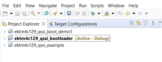
  • The TI reference design software collateral has everything you need. I don't know what else to provide. The software collateral has the bootloader with hook functions to initialize EPI and SPI Flash. Look at the bl_config.h file. The bootloader example is in ektm4c129_qssi_bootloader. The application example is in ektm4c129_qssi_boot_demo1.