This thread has been locked.

If you have a related question, please click the "Ask a related question" button in the top right corner. The newly created question will be automatically linked to this question.

MSP432E401Y: Using MSP432E401Y As XDS110

Part Number: MSP432E401Y
Other Parts Discussed in Thread: UNIFLASH, MSP-EXP432E401Y

We are looking to re-implement an XDS110 interface from the TMS320F280039 controlCard in a custom PCB design, in which the XDS110 implementation is running on an MSP432E401Y.

For proof-of-concept, we are working with MSP432E401Y LaunchPad and have been unsuccessful in getting the xdsdfu utility to recognize the chip as an XDS110 device.

Here are a few of the things we have tried:

- Using the XDSDFU utility from the command line (over USB), uploading the bootloader and firmware files individually and together.

- Using UniFlash from the XDS110 (over JTAG) on the LaunchPad (which is a TMC129ENCPDTI3), uploading the firmware file from XDSDFU.

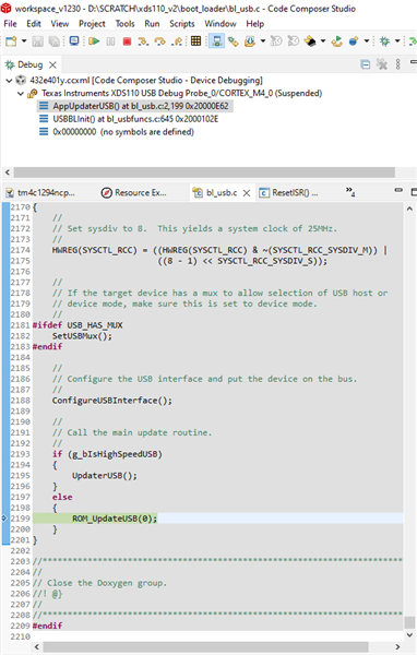
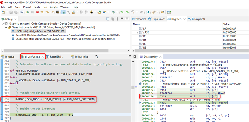
- Using LM Flash via USB after setting up the MSP432E401Y with a bootloader, whether that be the built-in ROM one, the one from XDSDFU, or the USB bootloader included as part of MSPWare (the SDK for the MSP432E4 chips), compiled in CCS.

- Commanding the a non-zero serial number of the MSP432E401Y with the xdsdfu utility prior to using it to download the bootloader or binary code

Various other combinations of these options (i.e. sequentially trying every combination of these techniques ), result in xdsdfu responding with

- "USB device not recognized" errors

-the device remaining in DFU mode

- the MSP432E401Y on the LaunchPad disappearing from the "$ xdsdfu -e" enumerate command;

In most cases we've managed to reprogram the device flash (according to UniFlash's "blank check" feature from the LaunchPad), but cannot manage to get the XDSDFU firmware working.

Any other things we should try?

  • For proof-of-concept, we are working with MSP432E401Y LaunchPad

    I assume after flashing the boot loader binary, you are connecting to the micro-USB port U7 on the launchpad to communicate to the MSP432E401Y. Is this correct? I'm not that will work. 

  • Yes, that's one of the methods we tried using. We checked through the schematics for both the C2000 control card XDS (which is a MSP432) and MSP432E401Y LaunchPad, and it looks like the USB ports do in fact connect to the same pins, which suggests to us that they should both be able to use XDSDFU like we were able to get working on the control card?

    Is there something else we ought to try? Trying to load the bootloader/firmware via UniFlash over JTAG was also unsuccessful.

  • We checked through the schematics for both the C2000 control card XDS (which is a MSP432) and MSP432E401Y LaunchPad, and it looks like the USB ports do in fact connect to the same pins, which suggests to us that they should both be able to use XDSDFU like we were able to get working on the control card?

    I assume you are referring to J1:A of the F280039C controlcard, that port can be configured to provide XDS110 emulation and USB-to-UART communication. I do not know enough about the hardware specifics of the LaunchPad and will need to follow up with engineering for more details.

  • Yes, that is correct.

    To clarify, our primary goal at this stage is to be able to plug into the micro-USB port (U7) of the LaunchPad and have the XDSDFU utility recognize the target MSP432E401Y (U1) device as an XDS device (with the correct firmware version) when we command "xdsdfu -e". 

    What I meant by the last comment is that we were able to use the J1:A USB-C connector of the F280039C control card to update the firmware of the MSP432E401Y (U1:A) device, as you suggested should work. From this, we assumed that it should be possible to do something similar for the LaunchPad, as the connections look to be the same based on the schematics.

  • What I meant by the last comment is that we were able to use the J1:A USB-C connector of the F280039C control card to update the firmware of the MSP432E401Y (U1:A) device, as you suggested should work. From this, we assumed that it should be possible to do something similar for the LaunchPad, as the connections look to be the same based on the schematics.

    I will bring this thread to the attention of the device experts to confirm the above.

  • Oh, I should also mention that we have been able to get Windows Device Manager to recognize the LaunchPad MSP432E401Y device by grounding the JTAG (J101) TDO pin on startup, and "xdsdfu -e" does recognize the device as one in DFU mode (with a serial number of all zeros).

    However, when we try to use XD1SDFU to upload either the XDS bootloader or the XDS firmware to the device, the process fails, typically with an unknown error (-4). In other cases, XDSDFU is supposedly able to successfully upload the firmware (never the bootloader), but then does not detect the target MSP432E401Y on the LaunchPad at all (either in DFU mode or as a XDS).

  • Engineering created a custom xdsdfu utility which can print out additional diagnostics via an additional "-t" option, Please give it a try and provide the additional diagnostics information when you get stuck:

    xdsdfu.zip

  • Thank you for the new upgrade utility. Unfortunately, we were not able to get the firmware update working using it, though we did get some error codes that may be of use.

    In general, we first wiped the LaunchPad MSP432E401Y (U1:A) from the known XDS110 (TM4C129) using UniFlash/JTAG to get a known-blank starting point, then uploaded the firmware and bootloader included with our original XDSDFU download (firmware version 3.0.0.25, bootloader version is not listed but was supposedly last modified 3/10/23) using the new XDSDFU utility you provided with the "-t" flag enabled.

    In both cases, we first got a header similar to this:

    LMDFUDeviceOpen 0
    Downloading 8 bytes from 0x000000000014FC78
    State on completion IDLE, status STATUS_OK
    LMDFUDeviceParamsGet 0x0000000000613580
    Downloading 8 bytes from 0x000000000014FCA0
    State on completion IDLE, status STATUS_OK
    Downloading .\firmware_3.0.0.25.bin to device...
    LMDFUDeviceIsValidImage 0x0000000000613580 0x0000000000645FA0 315357
    Image is not fully DFU-wrapped. Downloading as binary
    Downloading image to flash.... LMDFUDownloadBin 0x0000000000613580 0x0000000000645FA0 315357 Verify
    Downloading 8 bytes from 0x000000000014FC18
    State on completion DNLOAD_IDLE, status STATUS_OK
    Downloading 1024 bytes from 0x0000000000645FA0

    Then a number of outputs along the lines of:

    State on completion DNLOAD_IDLE, status STATUS_OK
    Downloading 1024 bytes from 0x0000000000645FA0

    And, finally, an error message at the end:

    Completed.
    LMDFUDeviceClose 0x0000000000613580
    Downloading 8 bytes from 0x000000000014FCC0
    Error 6 from Endpoint0Transfer

    The device remained in DFU mode when we tried uploading the firmware, but after doing so with the bootloader, no devices were found when we ran "$ xdsdfu -e". Hope this helps.

  • Hi Ki! David here from the same company as Ethan, I'll be taking over helping write some of the comments about the different things we've tried.

    I just wanted to provide a little more clarity on the above comment (we read it over again and it's somewhat ambiguous in some places) with a more specific list of the steps/commands we used:

    1. Erase the target MSP432E401Y using UniFlash over JTAG from the TM4C129-based XDS110
    2. Unplug the USB cable leading to the TM4C and the JTAG jumpers
    3. Ground the JTAG TDO pin on the MSP432E401Y side before plugging in a USB cable to that end of the LaunchPad
    4. In XDSDFU, run "$ xdsdfu -e" to verify that the device indeed shows up in DFU mode
    5. Upload the bootloader/firmware via "$ xdsdfu -b boot_loader.bin -r -v -t" and "$ xdsdfu -f firmware_3.0.0.25.bin -r -v -t" respectively
    6. Run "$ xdsdfu -e" to check and see the new status of the target MSP432E401Y device

    As mentioned, we'd like to have been able to try uploading the bootloader and then firmware via XDSDFU, but the utility does not recognize the device once the bootloader was uploaded, presumably due to the error we encountered (6) when individually uploading each of the files to the blank device.

  • I tried steps on my launchpad. Some comments:

    I followed steps #1-4 as you did with the exception of #2 below:

    For #2, I pulled off the jumpers related to JTAG on J101 and left the 3.3V, 5V and GND alone. Then I plugged the USB cable back in to provide power. NOte that the USB cable is not plugged in to the PC but instead a separate power supply. How are you supplying power to the board of not via the USB connection on the JTAG side.

    For #5: After I flash the bootloader binary via xdsdfu, I get a "USB device not recognized" error and xdsdfu no longer detects any devices. This sounds like what happened to you:

    As mentioned, we'd like to have been able to try uploading the bootloader and then firmware via XDSDFU, but the utility does not recognize the device once the bootloader was uploaded

    Looks like I can reproduce the issue. I'll see if I can have the engineers take a closer look at my environment

  • Prior to step 2 we had the LaunchPad plugged in to our PC via the USB101 port, with the GND, 5V, 3.3V, and JTAG (TMS, TCK, TDO, TDI) jumpers installed. This is the configuration we used to erase the target MSP432E401Y device and check that it is blank.

    Afterwards, we had the LaunchPad plugged in via the U7 USB port with the JTAG jumpers removed, keeping the jumpers for GND, 5V, and 3.3V as they were during the blanking process (it seems that the target MSP432E401Y does not receive 3.3V power otherwise). This is the configuration we used to try and flash the bootloader/firmware, using both the power and data from a PC over the U7 USB port.

    In both configurations we left all the middle jumpers JP2, JP4, JP5, JP6, and JP7 installed; for the 5V power jumpers J1, we kept 5V-OTG and 5V-XDS installed, but did not connect the pins for 5V-EXT.

  • Ok, yes that is similar to my setup.

    I have been investigating this issue with one of the CCS engineers. When stepping through the flashed boot loader with CCS, we can see that everything looks good until when setting to the below line during USB configuration:

    Stepping past this point will cause the program to run into the weeds. We feel there is some issue with trying to use the USB port on the launchpad but otherwise currently lack further details.

  • Ah, glad to hear that we've found the source of the problem! Best of luck figuring it out, we'll be anxiously awaiting a solution.

  • More details:

    Looks like the exact location of where things go wrong is in the highlighted assembly instruction below at address (0x20001190).

    This occurs in the USBBLInit() function which (according to the comments) is to initialize the boot loader USB functions and place the DFU device onto the USB bus. When stepping over that asm instruction, the host computer seems to lose connection to the attached MSP432E device detected earlier.

    I still feel that the root cause is the way the USB port on the launchpad is wired up. There could be something there that is preventing this from working as expected.

    Please note that debugging the USB port on the launchpad is something beyond the expertise of the software tools team. We are seeing if we can come up with more information. To set expectations correctly, I don't anticipate a quick resolution on this.

    thanks

    ki

  • Thanks for digging down to the next level - it gave me a potential clue as I was going through some of the schematics on the F28003x controlCARD (which runs the XDS110 firmware on the MSP432E401Y).

    On the F28003x control card, there is a digital input pin on the MSPE401Y that seems to be driven from the PC's USB connection (image below). This pin seems to have a special purpose, as the MSP432E401Y datasheet 5.15.9 states "All GPIO signals are 3.3-V tolerant, except for PB1 (USB0VBUS) which is 5-V tolerant." and "PB1 is used for the USB0VBUS signal, which requires a 5-V input."

    Does the TI team know if this USB-purpose pin (or any other pins) on the MSP-EXP432E401Y LaunchPad that need to be connected to make it compatible with the `xdsdfu` utility and/or XDS110 firmware?

  • A secondary question on the USB0VBUS signal and the 5V requirement: it it required to be 5V by the USB standard, or by the implementation of the MSP432E401Y USB peripheral?

    In other words, would the MSP432E401Y be able to recognize host connected/disconnected status if it were driven by a 3.3V signal?

  • I lack the expertise to answer these specific hardware questions. I will bring this thread to the attention of the device experts 

  • A secondary question on the USB0VBUS signal and the 5V requirement: it it required to be 5V by the USB standard, or by the implementation of the MSP432E401Y USB peripheral?

    By standard, it must be 5V input. PB1 is for USB0VBUS. This signal is used during the session request protocol. This signal allows the USB PHY to both
    sense the voltage level of VBUS, and pull up VBUS momentarily during VBUS pulsing. When PB1 is used for USB0VBUS function, it needs to be 5V input. If you apply 3.3V then it may not meet the Vih of the input pin. 

    Here is another note about PB1. See section 4.3.1 of MSP432E system design guideline. https://www.ti.com/lit/pdf/slaa770

  • We're approaching our deadline to order the boards with the MSP432E401Y we want to use as an XDS110, and wanted to check in with the status of the trouble we've been having flashing these chips. Are there any updates with regards to the source of the issue? 

    Since we're able to use XDSDFU with no issue on the MSP432E401Y used as an XDS110 for the C28003xC ControlCard, we figure that the issue might have to do with some difference in the internal wiring between the implementation there and on the MSP432E401Y LaunchPad (as opposed to some software bug, though that is also certainly possible). Is there some specific section of each schematic worth diving into to see if there are differences?

    We further chased down the idea of whether pin 96 (PB1) was connected to 5V, but it seems as though this connection has already been made on both the LaunchPad and ControlCard.

  • Since we're able to use XDSDFU with no issue on the MSP432E401Y used as an XDS110 for the C28003xC ControlCard, we figure that the issue might have to do with some difference in the internal wiring between the implementation there and on the MSP432E401Y LaunchPad (as opposed to some software bug, though that is also certainly possible).

    I would agree with this. MSP432E401Y is a known supported device for XDS110 implementation and there are many existing designs that use it (like the controlcard you mentioned). 

    Is there some specific section of each schematic worth diving into to see if there are differences?

    Again, this section is beyond my area of expertise. I would defer to Charles or anyone on the device/hardware team.

    All we (the software team that maintains the XDS110 firmware) can claim is that MSP432E401Y is a supported device for XDS110 implementation. We are not in the position to officially support attempts to repurpose an existing MSP432E401Y LaunchPad to emulate an XDS110 debug probe. 

  • We wanted to give this thread a bit of a bump, since we're still stumped here on our end.

    We were able to figure out that the PB1 USB0VBUS pin is indeed connected to 5V on both the LaunchPad and ControlCard...does the hardware team have any other ideas as to how the devices on the two development kits might be wired differently?

  • Hi David,

      I'm supporting TM4C MCU only. I can't really speak for C2000 ControlCard. 

  • Thanks for the update, Charles; we'll keep looking into it on our end, but do let us know if there's anything you can think of that might be different between the two implementations. One question though: is there any reason you can think of that might cause a loss of connection to the attached MSP432E MCU device via USB per the debugging work Ki did previously? Or perhaps someone else we should contact who might have more insight on the issue?

  • And on that note: Ki, do you happen to have any insight on what types of things might cause a loss of connection during this instruction in particular? Could it possibly be a power loss/instability issue, or should we look more on the data side of things?

  • Hi David,

    Unfortuntately I don't have much more to offer on this issue. Sorry.

    ki

  • Is there someone else I might be able to contact with regards to this? Happy to email too if the forum isn't the right place for such a specific topic.

  • Is there someone else I might be able to contact with regards to this?

    I do not. The device experts are aware of this thread hence if they have any further comment they can reply to this thread.