Part Number: TMS570LS3137
Other Parts Discussed in Thread: HALCOGEN
Hello! My name is Leandro
In my current project, I'm working with a TMS570LS3137 microcontroller, and I need to turn off some
peripherals to save power (I mean, disable the peripheral clock). I found this aplication report that
informs how to do that: www.ti.com/.../spna173.pdf
ts=1681316353136&ref_url=https%253A%252F%252Fwww.google.com%252F . It's named "Reduction
of power consumtion for TMS570LS3137".
The report suggests using the Peripheral Power-Down Set Register 0 (PSPWRDWNSET0) and
Peripheral Power-Down Set Register 1 (PSPWRDWNSET1) to disable the clocks of a given peripheral.
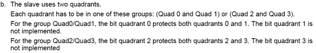
Those 32 bit register represent a "Peripheral Select" every 4 bits, and these 4 bits represent quadrants of
the whole peripheral. Fortunately, the aplication report presents a table (table 5) that explains which bits
of those registers one must set to effectively disable the clock of certain peripheral.
The report also gives an example:
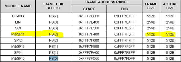
"Example Disabling MibSPI1
The corresponding PS decodes all addresses between 0xFFF7F400 and 0xFFF7F7FF. MIBSPI1 and
SPI2 are mapped to this PS2 as following:
• PS2 quadrant 0 and quadrant 1 are for MibSPI1 for a total of 512 bytes
• PS2 quadrant 2 and quadrant 3 are for SPI2 for a total of 512 bytes
To disable the MibSPI1, bits 8 and 9 of the Peripheral Power-Down Set Register 0 (PSPWRDWNSET0)
have to be set."
The problem I'm having is that I'm not being able to set those bits. In fact, not only those, but a lot more.
For a simple example, I tried setting all bits in the register, and only a few did respond.
This is what I can read of the PSPWRDWNSET0 register after tryng to set all bits:
01010000000100010000000100000101b
We can see that bits 8 and 9 did not get setted, so the example of turning off MibSPI1 failed for me.
I was in supervisor mode when I tried to set all of those bits.
So the question is, why doesn't all the bits get setted? How can I know if a peripheral clock indeed got
disabled or not?
Regarding the project I used, I just did the following:
1- Created a new Compose Studio Code project with the TMS570LS3137 as target.
2-Created a new HalCoGen project (associated with the CSS project) and disabled all available drivers
of peripherals. I generated the code with those settings. I tried with and without FreeRTOS.
3- The only thing that I added to the main function was to set all bits in the Peripheral Power-Down Set
Register 1 (PSPWRDWNSET1) and Peripheral Power-Down Set Register 0 (PSPWRDWNSET0)
Can you help me realizing what am I doing wrong?
Thanks a lot in advance!