This thread has been locked.

If you have a related question, please click the "Ask a related question" button in the top right corner. The newly created question will be automatically linked to this question.

MSPM0G3507: ADC interrupt for MEM1 & MEM2 is not generating

Part Number: MSPM0G3507
Other Parts Discussed in Thread: SYSCONFIG

Hello,

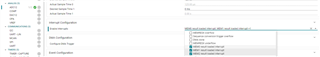
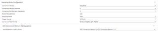
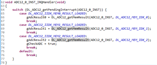
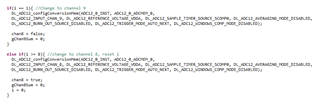
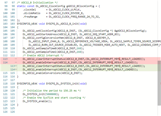
I have connected Ch2, Ch3 and Ch7 to ADC0. Selected conversion memory as MEM0, MEM1 & MEM2 & set MEM0 as start address. I am getting interrupt for MEM0 loaded but not for MEM1 & MEM2. Need a help related to configurations for mem1 and mem2.

Thanks & regards,

Amruta 

  • Hi Amruta,

    Under the "Interrupt" configuration section of the ADC module in Sysconfig can you verify that MEM0 result loaded interrupt, MEM1 result loaded interrupt, and MEM2 result loaded interrupt is set.

    Also make sure the ending address for conversion is set to 2.

    Your interrupt handler should also have the checks for MEM0, MEM1, and MEM2 result loaded.

    You don't need to get the memory result inside the ISR, but it was an easy way for me to verify that the interrupts were working.

    Regards,

    Luke

  • Hello Luke,

    Thank you for your quick response.  I had interrupt settings.

    But instead of using sequence conversion mode, I want to use single convesion.

    Is this work with single conversion mode?

    Regards,

    Amruta

  • Hi Amruta,

    You can use the single conversion mode but, you would need to call a couple of functions inside of your code.

    1. You will need to configure the conversion memory(s) this can be done with the DL_ADC12_configConversionMem function.
    2. Enable the memory address interrupts with the DL_ADC12_enableInterrupt function
    3. You need to change the start address for the ADC readings with DL_ADC12_setStartAddress before you do a conversion so the ADC will do a single conversion on that memory address.

    If you only want 1 channel sampled at a time it might be easier to just change the Conversion Memory0 then proceed as normal. I've done this before and below is how I alternated sampling 2 different channels.

    A small sysconfig tip as well -

    Clicking the <> symbol top right will allow you to see the generated code, when you change a setting it will show the changes. The config.c has the functions that are being called and the .h will have the pseudonym #defines

    This is really helpful when you want to do something that isn't necessarily available in Sysconfig. You can copy and paste the related functions into your main.c and change the parameters to fit your application flow.

    Regards,

    Luke

  • Hi Luke,
    Thank you for your reply. I tried by selecting MEM0 for 3 different channels, it's working.


    I tried to select MEM1 in existing sample program of single conversion, but it's not working for MEM1.
    below settings i had done,

    while (1) {
    DL_ADC12_startConversion(ADC12_0_INST);

    while (false == gCheckADC) {
    __WFE();
    }

    adcResult = DL_ADC12_getMemResult(ADC12_0_INST, DL_ADC12_MEM_IDX_1);

    if (adcResult > 0x7ff) {
    DL_GPIO_setPins(GPIO_LEDS_PORT, GPIO_LEDS_USER_LED_1_PIN);
    } else {
    DL_GPIO_clearPins(GPIO_LEDS_PORT, GPIO_LEDS_USER_LED_1_PIN);
    }
    gCheckADC = false;
    DL_ADC12_enableConversions(ADC12_0_INST);
    }
    }

    void ADC12_0_INST_IRQHandler(void)
    {
    switch (DL_ADC12_getPendingInterrupt(ADC12_0_INST)) {
    case DL_ADC12_IIDX_MEM1_RESULT_LOADED:
    gCheckADC = true;
    break;
    default:
    break;
    }
    }

    SYSCONFIG_WEAK void SYSCFG_DL_ADC12_0_init(void)
    {
    DL_ADC12_setClockConfig(ADC12_0_INST, (DL_ADC12_ClockConfig *) &gADC12_0ClockConfig);
    DL_ADC12_setStartAddress(ADC12_0_INST,1);
    DL_ADC12_configConversionMem(ADC12_0_INST, ADC12_0_ADCMEM_1,
    DL_ADC12_INPUT_CHAN_2, DL_ADC12_REFERENCE_VOLTAGE_VDDA, DL_ADC12_SAMPLE_TIMER_SOURCE_SCOMP0, DL_ADC12_AVERAGING_MODE_DISABLED,
    DL_ADC12_BURN_OUT_SOURCE_DISABLED, DL_ADC12_TRIGGER_MODE_AUTO_NEXT, DL_ADC12_WINDOWS_COMP_MODE_DISABLED);
    DL_ADC12_setPowerDownMode(ADC12_0_INST,DL_ADC12_POWER_DOWN_MODE_MANUAL);
    DL_ADC12_setSampleTime0(ADC12_0_INST,500);
    /* Enable ADC12 interrupt */
    DL_ADC12_clearInterruptStatus(ADC12_0_INST,(DL_ADC12_INTERRUPT_MEM1_RESULT_LOADED));
    DL_ADC12_enableInterrupt(ADC12_0_INST,(DL_ADC12_INTERRUPT_MEM1_RESULT_LOADED));
    DL_ADC12_enableConversions(ADC12_0_INST);
    }

    Thanks, and regards,

    Amruta

  • Hello Amruta,

    I just ran the example and was able to get readings. I'm assuming above you have the NVIC_EnableIRQ(ADC12_0_IRQN); call.

    I'm attaching the code that I used, if you could confirm that you are able to read data.

    E2E Test.zip

    Regards,

    Luke