This thread has been locked.
If you have a related question, please click the "Ask a related question" button in the top right corner. The newly created question will be automatically linked to this question.
Hi BU,
The background is customer found that their timer-based periodical tasks not run anymore after their board working continuously for 9 days.
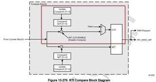
From my understanding, there are 2 stages for handling the interrupt inside the chip hardware: RTI interrupt generation logic + VIM interrupt prioritizing and processing. After RTI INT condition is met, the VIM IRQ STS should be set and waiting to be active.
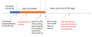
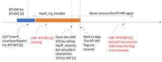
I wrote a program to understand the hardware behavior. And it seems that from hardware behavior, the corresponding VIM IRQ STS will not set if the previous RTI INT Flag is not cleared. To better manifest this, please see following fig:
And the test codes is attached: timer_int_not_handled.zip
I have following thoughts:
1). the root reason for this issue is that when the previous RTI INT flag is not cleared, the latter RTI INT will not issue to VIM to set the VIM INT STS, right?
2). change the attribute of type from Pulse to Level to solve this problem;
3). enable the periodical flag clearing feature in RTI to solve this problem.
Please check this issue and give your suggestions, thanks.
BR,
Will
Hi Will,
I tried the SW you provided and I could not find the exact issue and I am still working on it but I went on to try the example and this works as per the expectations - https://software-dl.ti.com/mcu-plus-sdk/esd/AM263X/latest/exports/docs/api_guide_am263x/EXAMPLES_KERNEL_DPL_INTERRUPT_PRIORITIZATION.html
.../am263x-cc/r5fss0-0_freertos/example.syscfg | 6 +++--- .../dpl/interrupt_prioritization/interrupt_prioritization.c | 12 ++++++++++++ 2 files changed, 15 insertions(+), 3 deletions(-) diff --git a/examples/kernel/dpl/interrupt_prioritization/am263x-cc/r5fss0-0_freertos/example.syscfg b/examples/kernel/dpl/interrupt_prioritization/am263x-cc/r5fss0-0_freertos/example.syscfg index 0946fe00bb..935fe6fc24 100644 --- a/examples/kernel/dpl/interrupt_prioritization/am263x-cc/r5fss0-0_freertos/example.syscfg +++ b/examples/kernel/dpl/interrupt_prioritization/am263x-cc/r5fss0-0_freertos/example.syscfg @@ -2,7 +2,7 @@ * These arguments were used when this file was generated. They will be automatically applied on subsequent loads * via the GUI or CLI. Run CLI with '--help' for additional information on how to override these arguments. * @cliArgs --device "AM263x_beta" --package "ZCZ" --part "AM263x" --context "r5fss0-0" --product "MCU_PLUS_SDK@07.03.01" - * @versions {"tool":"1.10.0+2163"} + * @versions {"tool":"1.14.0+2667"} */ /** @@ -49,17 +49,17 @@ mpu_armv74.size = 21; timer1.$name = "CONFIG_TIMER0"; timer1.timerCallback = "timer0_ISR"; -timer1.intrPriority = 2; timer1.usecPerTick = 500000; timer2.$name = "CONFIG_TIMER1"; timer2.timerCallback = "timer1_ISR"; -timer2.intrPriority = 3; timer2.usecPerTick = 500000; +timer2.intrPriority = 3; timer3.$name = "CONFIG_TIMER2"; timer3.timerCallback = "timer2_ISR"; timer3.usecPerTick = 500000; +timer3.intrPriority = 2; /** * Pinmux solution for unlocked pins/peripherals. This ensures that minor changes to the automatic solver in a future diff --git a/examples/kernel/dpl/interrupt_prioritization/interrupt_prioritization.c b/examples/kernel/dpl/interrupt_prioritization/interrupt_prioritization.c index 2961572a3a..0e250ce512 100644 --- a/examples/kernel/dpl/interrupt_prioritization/interrupt_prioritization.c +++ b/examples/kernel/dpl/interrupt_prioritization/interrupt_prioritization.c @@ -153,11 +153,13 @@ void interrupt_prioritization(void *args) /* Highest proiority ISR */ void timer0_ISR(void) { + #if 0 /* Check if the previous trace element is as expected */ if(gTraceISR[(gTraceISRIndex-1) % TRACE_SIZE] != 0xA1) { status = SystemP_FAILURE; } + #endif /* Add Timer 0 ISR start to trace */ gTraceISR[gTraceISRIndex % TRACE_SIZE] = 0xA0; @@ -169,11 +171,13 @@ void timer0_ISR(void) gLoopVar0--; } + #if 0 /* Check if the previous trace element is as expected */ if(gTraceISR[(gTraceISRIndex-1) % TRACE_SIZE] != 0xA0) { status = SystemP_FAILURE; } + #endif /* Add Timer 0 ISR end to trace */ gTraceISR[gTraceISRIndex % TRACE_SIZE] = 0xB0; @@ -183,11 +187,13 @@ void timer0_ISR(void) /* Medium proiority ISR */ void timer1_ISR(void) { + #if 0 /* Check if the previous trace element is as expected */ if(gTraceISR[(gTraceISRIndex-1) % TRACE_SIZE] != 0xA2) { status = SystemP_FAILURE; } + #endif /* Add Timer 1 ISR start to trace */ gTraceISR[gTraceISRIndex % TRACE_SIZE] = 0xA1; @@ -199,11 +205,13 @@ void timer1_ISR(void) gLoopVar1--; } + #if 0 /* Check if the previous trace element is as expected */ if(gTraceISR[(gTraceISRIndex-1) % TRACE_SIZE] != 0xB0) { status = SystemP_FAILURE; } + #endif /* Add Timer 1 ISR end to trace */ gTraceISR[gTraceISRIndex % TRACE_SIZE] = 0xB1; @@ -213,6 +221,7 @@ void timer1_ISR(void) /* Lowest proiority ISR */ void timer2_ISR(void) { + #if 0 /* * Since this is the ISR which gets executed first, we make sure that this is not * its initial execution and then check if the previous trace element is as expected. @@ -221,6 +230,7 @@ void timer2_ISR(void) { status = SystemP_FAILURE; } + #endif /* Add Timer 2 ISR start to trace */ gTraceISR[gTraceISRIndex % TRACE_SIZE] = 0xA2; @@ -232,11 +242,13 @@ void timer2_ISR(void) gLoopVar2--; } + #if 0 /* Check if the previous trace element is as expected */ if(gTraceISR[(gTraceISRIndex-1) % TRACE_SIZE] != 0xB1) { status = SystemP_FAILURE; } + #endif /* Add Timer 2 ISR end to trace */ gTraceISR[gTraceISRIndex % TRACE_SIZE] = 0xB2;
Try playing around by changing the priority of the interrupts of the different timers via syscfg and understand the working of interrupts and VIM.
Hope it helps.
Best Regards,
Aakash
Hi Aakash,
The interrupt priority of timer used for ClockP SW component is fixed inside the ClockP driver and can't be configured by SysConfig.
The main problem now is why Timer's interrupt can't issue to VIM after the last interrupt flag is not cleared. The project I provided is to illustrate this situation. And the fig I submitted is to demonstrate the timing sequence for this situation.
Please help confirm with design team on this RTI hardware behavior. I think for issuing interrupt into VIM, the raw RTI interrupt signal should have a rising edge, and this is why if the flag is not cleared, the following interrupt can't issue to VIM.
It is common in application that the RTI interrupt can not be timly cleared due to complex interrupt tasks, e.g. control loop. So from my view, it will be better if the RTI driver/ClockP SW can use the hardware feature- periodically clear the interrupt flag as following:
Regards,
Will
I dont have anything extra to add here. You have rightly understood the working.
VIM supports a Level or pulse interrupt (and one must configure VIM accordingly)
1. If Level, then first the source has to be cleared and then VIM has to be cleared. This way VIM will not get a false extra interrupt
2. If Pulse, then you can clear in any order. But the IP has to strictly generate a pulse interrupt. It it should generate another edge for VIM to register it as a new interrupt.
In this example the RTI is generating a level interrupt. You can use the autoclear feature of RTI and make it into a pulse. Or configure VIM to treat it as a level interrupt. Both works based on how you want the system to setup.
Regards
Prithvi