This thread has been locked.

If you have a related question, please click the "Ask a related question" button in the top right corner. The newly created question will be automatically linked to this question.

TM4C129ENCPDT: How to configure Hwi for gpio in TI RTOS

Part Number: TM4C129ENCPDT
Other Parts Discussed in Thread: EK-TM4C1294XL

Hi,

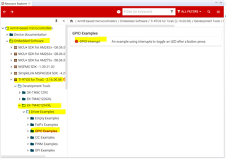
I'm using TM4C129ENCPDT mcu to develop one of my projects on which I need to integrate TI RTOS. For that I need to configure hardware interrupt for 2 gpio pins. I configure as pre shown in the user guide but interrupt is not working. I made interrupt without using TI RTOS but not possible with Rtos.

1. How can configure the gpio for this as external hardware interrupt?

2. Can you share any sample code for this?

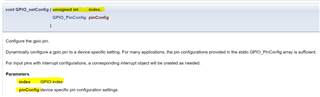
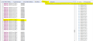
3. The functions in TI RTOS libraries are not provide arguments for both port and pin. Is any specific  declaration present in it? or how can declare the port and pin?

GPIO_setConfig(GPIO_PIN_0, GPIO_CFG_INPUT | GPIO_CFG_IN_INT_BOTH_EDGES); 

This is one of the function for configure the gpio pin. Is this correct way? Where we mention port?

The following is my code,

#define CT_SESR GPIO_PORTM_BASE | GPIO_PIN_0

bool motor_on;
Hwi_Handle hwiHandle;

/* GPIO interrupt handler */
void gpioInterruptHandler(uintptr_t arg)
{
uint32_t status = GPIOIntStatus(GPIO_PORTM_BASE, true);
if(status & (GPIO_PORTM_BASE | GPIO_PIN_0 | GPIO_PIN_7))
{
// find the interrupt status
motor_on = !(GPIOPinRead(GPIO_PORTM_BASE, GPIO_PIN_0)) | GPIOPinRead(GPIO_PORTM_BASE, GPIO_PIN_7);

// clear interrupt flag
GPIO_clearInt(CT_SESR);
}
}

int main(void)
{
/* Initialize TI-RTOS and drivers */
Board_initGeneral();

/* Initialize GPIO pin */
GPIO_init();

GPIO_setConfig(CT_SESR, GPIO_CFG_INPUT | GPIO_CFG_IN_INT_BOTH_EDGES);
 GPIO_setCallback(CT_SESR, gpioInterruptHandler);
// /* Enable GPIO interrupt */
Hwi_Params hwiParams;
Hwi_Params_init(&hwiParams);
hwiParams.arg =CT_SESR;
hwiHandle = Hwi_create(INT_GPIOM, gpioInterruptHandler, &hwiParams, NULL);
 GPIO_enableInt(CT_SESR);
 /* Start TI-RTOS scheduler */
BIOS_start();

return 0;
}
  • Hi,

     You can import a GPIO interrupt example from C:\ti\tirtos_tivac_2_16_00_08\resources\ek_tm4C1294XLEvaluationKit\driverExamples\tiDriverExamples\gpioExamples or 

      you can download the same example from Resource Explorer from within CCS. See below. 

    This examples uses PJ0 and PJ1 for generating interrupt on rising edge. You can modify the EK-TM4C1294XL.c file to adapt to the pins for your application to generate interrupts. Below is a code snippet. 

    /*
    * =============================== GPIO ===============================
    */
    /* Place into subsections to allow the TI linker to remove items properly */
    #if defined(__TI_COMPILER_VERSION__)
    #pragma DATA_SECTION(GPIOTiva_config, ".const:GPIOTiva_config")
    #endif

    #include <ti/drivers/GPIO.h>
    #include <ti/drivers/gpio/GPIOTiva.h>

    /*
    * Array of Pin configurations
    * NOTE: The order of the pin configurations must coincide with what was
    * defined in EK_TM4C1294XL.h
    * NOTE: Pins not used for interrupts should be placed at the end of the
    * array. Callback entries can be omitted from callbacks array to
    * reduce memory usage.
    */
    GPIO_PinConfig gpioPinConfigs[] = {
    /* Input pins */
    /* EK_TM4C1294XL_USR_SW1 */
    GPIOTiva_PJ_0 | GPIO_CFG_IN_PU | GPIO_CFG_IN_INT_RISING,
    /* EK_TM4C1294XL_USR_SW2 */
    GPIOTiva_PJ_1 | GPIO_CFG_IN_PU | GPIO_CFG_IN_INT_RISING,

    /* Output pins */
    /* EK_TM4C1294XL_USR_D1 */
    GPIOTiva_PN_1 | GPIO_CFG_OUT_STD | GPIO_CFG_OUT_STR_HIGH | GPIO_CFG_OUT_LOW,
    /* EK_TM4C1294XL_USR_D2 */
    GPIOTiva_PN_0 | GPIO_CFG_OUT_STD | GPIO_CFG_OUT_STR_HIGH | GPIO_CFG_OUT_LOW,
    };

    /*
    * Array of callback function pointers
    * NOTE: The order of the pin configurations must coincide with what was
    * defined in EK_TM4C1294XL.h
    * NOTE: Pins not used for interrupts can be omitted from callbacks array to
    * reduce memory usage (if placed at end of gpioPinConfigs array).
    */
    GPIO_CallbackFxn gpioCallbackFunctions[] = {
    NULL, /* EK_TM4C1294XL_USR_SW1 */
    NULL /* EK_TM4C1294XL_USR_SW2 */
    };

    /* The device-specific GPIO_config structure */
    const GPIOTiva_Config GPIOTiva_config = {
    .pinConfigs = (GPIO_PinConfig *)gpioPinConfigs,
    .callbacks = (GPIO_CallbackFxn *)gpioCallbackFunctions,
    .numberOfPinConfigs = sizeof(gpioPinConfigs)/sizeof(GPIO_PinConfig),
    .numberOfCallbacks = sizeof(gpioCallbackFunctions)/sizeof(GPIO_CallbackFxn),
    .intPriority = (~0)
    };

    Also refer to section 5.5 of TI-RTOS user's guide on using GPIO drivers. 

    https://www.ti.com/lit/pdf/SPRUHD4M

  • Hi Charles,

    The issue is remain same. I try to configure the gpio as you mentioned. But the result is still same. I think something is missing in it.

  • Hi,

      Reading your earlier code again, I see the below #define. 

    #define CT_SESR GPIO_PORTM_BASE | GPIO_PIN_0

    What you have above is wrong because when you call any I2C function it becomes like below. For example,

    GPIO_setConfig(GPIO_PORTM_BASE | GPIO_PIN_0, GPIO_CFG_INPUT | GPIO_CFG_IN_INT_BOTH_EDGES); // this is wrong. 

    Refer to user's guide for GPIO_setConfig. You need to provide a index to GPIO_setConfig. The index is already defined
    for Tiva device in TPIOTiva.h. See below snippets.


    If you want to dynamically configure PM0 then you could do:

    #define CT_SESR GPIOTiva_PM_0


    The reason is that GPIOTiva_PM_0 is already defined in GPIOTiva.h. See below.


    Why don't you just run the stock GPIO interrupt first? Firs run it and make sure it works. Afterward, you just modify
    EK-TM4C1294XL.c file

    From:
    GPIO_PinConfig gpioPinConfigs[] = {
    /* Input pins */
    /* EK_TM4C1294XL_USR_SW1 */
    GPIOTiva_PJ_0 | GPIO_CFG_IN_PU | GPIO_CFG_IN_INT_RISING,
    /* EK_TM4C1294XL_USR_SW2 */
    GPIOTiva_PJ_1 | GPIO_CFG_IN_PU | GPIO_CFG_IN_INT_RISING,

    To:
    GPIO_PinConfig gpioPinConfigs[] = {
    /* Input pins */
    /* EK_TM4C1294XL_USR_SW1 */
    GPIOTiva_PM_0 | GPIO_CFG_IN_PU | GPIO_CFG_IN_INT_BOTH_EDGES,
    /* EK_TM4C1294XL_USR_SW2 */
    GPIOTiva_PJ_1 | GPIO_CFG_IN_PU | GPIO_CFG_IN_INT_RISING,

    The stock example statically configures GPIO pins. If you want to dynamically configure GPIO pins you could do that too
    but you need to fix the
    CT_SESR I mentioned.