This thread has been locked.

If you have a related question, please click the "Ask a related question" button in the top right corner. The newly created question will be automatically linked to this question.

TM4C1294KCPDT: Writing arbitrary values to FlashROM

Part Number: TM4C1294KCPDT


I am investigating how to write to FlashROM from Firmware with TM4C1294KCPDT.

Is it possible to write arbitrary data to a specific address using the "TivaWareTm Peripheral Driver Library" by simply calling ROM_FlashProgram() without needing to lock the CPU or manipulate registers?
--------------------------------------------------
Example:
ROM area
0x00000000 - 0x0007FFFF
Program area
0x00000208 - 0x000298f9
Write destination ROM address
0x00040000

#include "rom.h"
UB data[] = { 0x31, 0x32, 0x33, 0x34 };
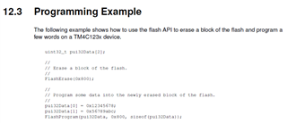
ROM_FlashProgram(data, 0x00040000, sizeof(data));
--------------------------------------------------
Also, referring to the TM4C1294KCPDT data sheet, I tried to perform the following FlashROM initialization processing at the beginning of the current Firmware.Is this necessary?

MEMTIM0 |= (0x06 << 6) | // Flash Bank Clock High Time 3.5 system clock periods
(0x00 << 5) | // Flash Bank Clock Edge rising
(0x05 << 0); // Flash Wait State 5 wait states
RSCLKCFG |= 0x80000000; // MEMTIM0 update
BOOTCFG |= 0x00000010; // 

Thank you very much.

  • I am investigating how to write to FlashROM from Firmware with TM4C1294KCPDT.

    Hi,

      It is possible. Please refer to the Peripheral Driver user's guide. Also see below.  Make sure that the flash page you want to program must be erased first if you are trying to program the same address again. 

     I'm not sure what is your purpose to write to the main flash. Please be aware that there is also a 6kB EEPROM for storing frequently used data. Unlike main flash, you don't need to erase EEprom by the application. It is all taken care of by the hardware in the background. From user's point of view, EEprom is more like a SRAM. You just read/write to it. Please refer to EEprom in the datasheet to see if it suits your application. Below is an example. 

    MEMTIM0 |= (0x06 << 6) | // Flash Bank Clock High Time 3.5 system clock periods
    (0x00 << 5) | // Flash Bank Clock Edge rising
    (0x05 << 0); // Flash Wait State 5 wait states
    RSCLKCFG |= 0x80000000; // MEMTIM0 update
    BOOTCFG |= 0x00000010; // 

    You do not need to do this manually. When you call SysCtlClockFreqSet() to configure the System Clock, all of wait states pertaining to flash memory is taken care of.