This thread has been locked.

If you have a related question, please click the "Ask a related question" button in the top right corner. The newly created question will be automatically linked to this question.

TM4C1292NCPDT: spi code not working for SSI3

Part Number: TM4C1292NCPDT


Hi,

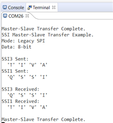
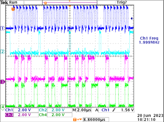
My example code for SPI (using SSI0) is working on TI Launchpad. See code below

#include <stdbool.h>
#include <stdint.h>
#include <inc/hw_types.h>
#include <inc/hw_ssi.h>
#include "inc/hw_memmap.h"
#include <driverlib/gpio.h>
#include "driverlib/pin_map.h"
#include "driverlib/ssi.h"
#include "driverlib/sysctl.h"
#include "driverlib/uart.h"
#include "utils/uartstdio.h"
#include <string.h>
//#include "main.h"


// Number of bytes to Send.
//
//*****************************************************************************
#define NUM_SSI_DATA 4
#define HB_ENABLE 0x0080
#define HB_CONFIG 0x0002


#ifdef DEBUG
void
__error__(char *pcFilename, uint32_t ui32Line)
{
}
#endif


uint32_t ui32SysClocks;
//*****************************************************************************
//
// This function sets up UART0 to be used for a console to display information
// as the example is running.
//
//*****************************************************************************
void InitConsole(void)
{
SysCtlPeripheralEnable(SYSCTL_PERIPH_UART0);
SysCtlPeripheralEnable(SYSCTL_PERIPH_GPIOA);
GPIOPinConfigure(GPIO_PA0_U0RX);
GPIOPinConfigure(GPIO_PA1_U0TX);
GPIOPinTypeUART(GPIO_PORTA_BASE, GPIO_PIN_0 | GPIO_PIN_1);
UARTStdioConfig(0, 9600, ui32SysClocks);
}

void InitSPI0(void){

SysCtlPeripheralEnable(SYSCTL_PERIPH_SSI0);
SysCtlPeripheralEnable(SYSCTL_PERIPH_GPIOA);

GPIOPinTypeGPIOOutput(GPIO_PORTA_BASE, GPIO_PIN_3|GPIO_PIN_2|GPIO_PIN_4);
GPIOPinTypeGPIOInput(GPIO_PORTA_BASE, GPIO_PIN_5);

SysCtlPeripheralEnable(SYSCTL_PERIPH_GPIOM);
SysCtlPeripheralEnable(SYSCTL_PERIPH_GPIOB);

GPIOPinTypeGPIOOutput(GPIO_PORTM_BASE, GPIO_PIN_5);
GPIOPadConfigSet(GPIO_PORTM_BASE, GPIO_PIN_5, GPIO_STRENGTH_12MA, GPIO_PIN_TYPE_STD_WPU );
GPIOPinWrite(GPIO_PORTM_BASE, GPIO_PIN_5, GPIO_PIN_5);//PULL UP

GPIOPinTypeGPIOOutput(GPIO_PORTB_BASE, GPIO_PIN_4);
GPIOPadConfigSet(GPIO_PORTB_BASE, GPIO_PIN_4, GPIO_STRENGTH_12MA, GPIO_PIN_TYPE_STD_WPU );
GPIOPinWrite(GPIO_PORTB_BASE, GPIO_PIN_4, GPIO_PIN_4);//PULL UP

GPIOPinConfigure(GPIO_PA2_SSI0CLK);
GPIOPinConfigure(GPIO_PA3_SSI0FSS);
GPIOPinConfigure(GPIO_PA4_SSI0XDAT0);//Tx
GPIOPinConfigure(GPIO_PA5_SSI0XDAT1);//Rx
GPIOPinTypeSSI(GPIO_PORTA_BASE, GPIO_PIN_5 | GPIO_PIN_4 | GPIO_PIN_3 | GPIO_PIN_2);
//SSIConfigSetExpClk(SSI0_BASE, ui32SysClocks, SSI_FRF_MOTO_MODE_2, SSI_MODE_MASTER, 40000000, 16);
//SSIConfigSetExpClk(SSI0_BASE, ui32SysClocks, SSI_FRF_MOTO_MODE_0, SSI_MODE_MASTER, 1500000, 16);
SSIConfigSetExpClk(SSI0_BASE, ui32SysClocks, SSI_FRF_MOTO_MODE_1, SSI_MODE_MASTER, 1500000, 16);//negative edge triggered
}

void SPI_write(const uint8_t* dataBuffer, uint8_t count){

while(count--){
SSIDataPut(SSI0_BASE, *dataBuffer++);
}
while(SSIBusy(SSI0_BASE));
}

//*****************************************************************************
//Main function Entry.
//
//*****************************************************************************
int
main(void)
{
bool pDO_Status[24];
uint8_t ui8Do_Source_Sink;

// spiConfigbus stSpiConfig;
// i2cConfigbus stI2cConfig;
uint16_t aui16SpiTxBuffer[2];
uint16_t aui16SpiRxBuffer[2][2];
uint8_t aui8I2cTxBuffer[3];
uint8_t aui8I2cRxBuffer[3];
uint8_t i;

uint8_t dataTX[4] = {0x40, 0x4F, 0x4F, 0x04};
//uint8_t dataTX = 0x40;
uint8_t count;

//ui32SysClocks = SysCtlClockFreqSet((SYSCTL_XTAL_25MHZ | SYSCTL_OSC_MAIN | SYSCTL_USE_PLL | SYSCTL_CFG_VCO_240), 120000000);
ui32SysClocks = SysCtlClockFreqSet((SYSCTL_XTAL_25MHZ | SYSCTL_OSC_MAIN | SYSCTL_USE_PLL | SYSCTL_CFG_VCO_480), 120000000);
InitConsole();

UARTprintf("SPI -> Master to Slave\n");
UARTprintf("SPI Bit_Rate: 16-bit\n\n");
InitSPI0();
SSIEnable(SSI0_BASE);

// GPIOPinWrite(GPIO_PORTM_BASE, GPIO_PIN_5, GPIO_PIN_5); //enable


dataTX[0] = (HB_ENABLE << 0 )| (HB_CONFIG << 0);//output high

SysCtlDelay(100);

SPI_write(dataTX, 1);

SysCtlDelay(100);//delay of

}

UARTprintf("Done transferring the data\r\n");
UARTprintf("----------------------------------------------------------------------");
UARTprintf("\r\n\n");

while(1);
}

But when I modify it for my requirement (using SSI3) ,it's not working on Launchpad. See the code modified for SSI3 below.

#include <stdbool.h>
#include <stdint.h>
#include <inc/hw_types.h>
#include <inc/hw_ssi.h>
#include "inc/hw_memmap.h"
#include <driverlib/gpio.h>
#include "driverlib/pin_map.h"
#include "driverlib/ssi.h"
#include "driverlib/sysctl.h"
#include "driverlib/uart.h"
#include "utils/uartstdio.h"
#include <string.h>
//#include "main.h"


// Number of bytes to Send.
//
//*****************************************************************************
#define NUM_SSI_DATA 4
#define HB_ENABLE 0x0080
#define HB_CONFIG 0x0002


#ifdef DEBUG
void
__error__(char *pcFilename, uint32_t ui32Line)
{
}
#endif


uint32_t ui32SysClocks;
//*****************************************************************************
//
// This function sets up UART0 to be used for a console to display information
// as the example is running.
//
//*****************************************************************************
void InitConsole(void)
{
SysCtlPeripheralEnable(SYSCTL_PERIPH_UART0);
SysCtlPeripheralEnable(SYSCTL_PERIPH_GPIOA);
GPIOPinConfigure(GPIO_PA0_U0RX);
GPIOPinConfigure(GPIO_PA1_U0TX);
GPIOPinTypeUART(GPIO_PORTA_BASE, GPIO_PIN_0 | GPIO_PIN_1);
UARTStdioConfig(0, 9600, ui32SysClocks);
}

void InitSPI0(void){

SysCtlPeripheralEnable(SYSCTL_PERIPH_SSI0);
SysCtlPeripheralEnable(SYSCTL_PERIPH_GPIOA);

GPIOPinTypeGPIOOutput(GPIO_PORTA_BASE, GPIO_PIN_3|GPIO_PIN_2|GPIO_PIN_4);
GPIOPinTypeGPIOInput(GPIO_PORTA_BASE, GPIO_PIN_5);

SysCtlPeripheralEnable(SYSCTL_PERIPH_GPIOM);
SysCtlPeripheralEnable(SYSCTL_PERIPH_GPIOB);

GPIOPinTypeGPIOOutput(GPIO_PORTM_BASE, GPIO_PIN_5);
GPIOPadConfigSet(GPIO_PORTM_BASE, GPIO_PIN_5, GPIO_STRENGTH_12MA, GPIO_PIN_TYPE_STD_WPU );
GPIOPinWrite(GPIO_PORTM_BASE, GPIO_PIN_5, GPIO_PIN_5);//PULL UP

GPIOPinTypeGPIOOutput(GPIO_PORTB_BASE, GPIO_PIN_4);
GPIOPadConfigSet(GPIO_PORTB_BASE, GPIO_PIN_4, GPIO_STRENGTH_12MA, GPIO_PIN_TYPE_STD_WPU );
GPIOPinWrite(GPIO_PORTB_BASE, GPIO_PIN_4, GPIO_PIN_4);//PULL UP

GPIOPinConfigure(GPIO_PA2_SSI0CLK);
GPIOPinConfigure(GPIO_PA3_SSI0FSS);
GPIOPinConfigure(GPIO_PA4_SSI0XDAT0);//Tx
GPIOPinConfigure(GPIO_PA5_SSI0XDAT1);//Rx
GPIOPinTypeSSI(GPIO_PORTA_BASE, GPIO_PIN_5 | GPIO_PIN_4 | GPIO_PIN_3 | GPIO_PIN_2);
//SSIConfigSetExpClk(SSI0_BASE, ui32SysClocks, SSI_FRF_MOTO_MODE_2, SSI_MODE_MASTER, 40000000, 16);
//SSIConfigSetExpClk(SSI0_BASE, ui32SysClocks, SSI_FRF_MOTO_MODE_0, SSI_MODE_MASTER, 1500000, 16);
SSIConfigSetExpClk(SSI0_BASE, ui32SysClocks, SSI_FRF_MOTO_MODE_1, SSI_MODE_MASTER, 1500000, 16);//negative edge triggered
}

void InitSPI3(void){

SysCtlPeripheralEnable(SYSCTL_PERIPH_SSI3);
SysCtlPeripheralEnable(SYSCTL_PERIPH_GPIOQ);
SysCtlPeripheralEnable(SYSCTL_PERIPH_GPIOP);

GPIOPinTypeGPIOOutput(GPIO_PORTQ_BASE, GPIO_PIN_2 | GPIO_PIN_0);
GPIOPinTypeGPIOInput(GPIO_PORTQ_BASE, GPIO_PIN_3);

GPIOPinTypeGPIOOutput(GPIO_PORTP_BASE, GPIO_PIN_1);//cs

GPIOPinTypeGPIOOutput(GPIO_PORTM_BASE, GPIO_PIN_5);
GPIOPadConfigSet(GPIO_PORTM_BASE, GPIO_PIN_5, GPIO_STRENGTH_12MA, GPIO_PIN_TYPE_STD_WPU );
GPIOPinWrite(GPIO_PORTM_BASE, GPIO_PIN_5, GPIO_PIN_5);//PULL UP

// GPIOPadConfigSet(GPIO_PORTM_BASE, GPIO_PIN_5, GPIO_STRENGTH_12MA, GPIO_PIN_TYPE_STD_WPU );
// GPIOPinWrite(GPIO_PORTM_BASE, GPIO_PIN_5, GPIO_PIN_5);//PULL UP

// GPIOPinTypeGPIOOutput(GPIO_PORTB_BASE, GPIO_PIN_4);
GPIOPadConfigSet(GPIO_PORTP_BASE, GPIO_PIN_1, GPIO_STRENGTH_12MA, GPIO_PIN_TYPE_STD_WPU );
GPIOPinWrite(GPIO_PORTP_BASE, GPIO_PIN_1, GPIO_PIN_1);//PULL UP

GPIOPinConfigure(GPIO_PQ0_SSI3CLK);
//GPIOPinConfigure(GPIO_PA3_SSI0FSS);
GPIOPinConfigure(GPIO_PQ2_SSI3XDAT0);//Tx
GPIOPinConfigure(GPIO_PQ3_SSI3XDAT1);//Rx
GPIOPinTypeSSI(GPIO_PORTQ_BASE, GPIO_PIN_0 | GPIO_PIN_3 | GPIO_PIN_2);
//SSIConfigSetExpClk(SSI0_BASE, ui32SysClocks, SSI_FRF_MOTO_MODE_2, SSI_MODE_MASTER, 40000000, 16);
//SSIConfigSetExpClk(SSI0_BASE, ui32SysClocks, SSI_FRF_MOTO_MODE_0, SSI_MODE_MASTER, 1500000, 16);
SSIConfigSetExpClk(SSI3_BASE, ui32SysClocks, SSI_FRF_MOTO_MODE_1, SSI_MODE_MASTER, 1500000, 16);//negative edge triggered
}

/*void SPI_write(const uint8_t* dataBuffer, uint8_t count){

while(count--){
SSIDataPut(SSI0_BASE, *dataBuffer++);
}
while(SSIBusy(SSI0_BASE));
}*/

void SPI_write_SSI3(const uint8_t* dataBuffer, uint8_t count){

while(count--){
SSIDataPut(SSI3_BASE, *dataBuffer++);
}
while(SSIBusy(SSI3_BASE));
}

//*****************************************************************************
//Main function Entry.
//
//*****************************************************************************
int
main(void)
{
bool pDO_Status[24];
uint8_t ui8Do_Source_Sink;

volatile uint32_t ui32Loop;

uint16_t aui16SpiTxBuffer[2];
uint16_t aui16SpiRxBuffer[2][2];
uint8_t aui8I2cTxBuffer[3];
uint8_t aui8I2cRxBuffer[3];
uint8_t i;

uint8_t dataTX[4] = {0x40, 0x4F, 0x4F, 0x04};
//uint8_t dataTX = 0x40;
uint8_t count;

//ui32SysClocks = SysCtlClockFreqSet((SYSCTL_XTAL_25MHZ | SYSCTL_OSC_MAIN | SYSCTL_USE_PLL | SYSCTL_CFG_VCO_240), 120000000);
ui32SysClocks = SysCtlClockFreqSet((SYSCTL_XTAL_25MHZ | SYSCTL_OSC_MAIN | SYSCTL_USE_PLL | SYSCTL_CFG_VCO_480), 120000000);
InitConsole();

UARTprintf("SPI -> Master to Slave\n");
UARTprintf("SPI Bit_Rate: 16-bit\n\n");

InitSPI3();
SSIEnable(SSI3_BASE);

dataTX[0] = (HB_ENABLE << 0 )| (HB_CONFIG << 0);//output high
GPIOPinWrite(GPIO_PORTP_BASE, GPIO_PIN_1, 0);

SysCtlDelay(100);

SPI_write_SSI3(dataTX, 1);

SysCtlDelay(100);//delay of

GPIOPinWrite(GPIO_PORTP_BASE, GPIO_PIN_1, GPIO_PIN_1);


UARTprintf("Done transferring the data\r\n");
UARTprintf("----------------------------------------------------------------------");
UARTprintf("\r\n\n");

while(1);
}

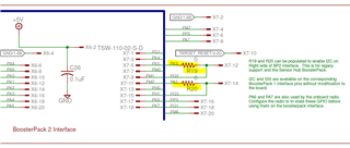
SSI3 is used in my schematic as below

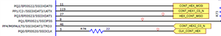
Can you please guide if there's anything in the code that needs to be changed for SSI3 to run?

Thanks,

Kiran

  • Hi,

      I think it is due to R19 nd R20 0-ohm resistor on the boosterpack. One option is to remove R19 and R20. Another option is to make sure that when you are PQ2 and PQ3, the PA3 and PA2 are configured as GPIO input only. You can not drive PA3 and PA2 when PA2 and PQ3 are used for SPI. 

  • Hi Charles,

    Will try after removing the R19 and R20,PA2 and PA3 are not driven in the modified code since I'm not calling the function InitSPI0 in which PA2 and PA3 are driven as outputs.

    Best Regards,

    Kiran

  • Why don't try to use the breakout board connector X11 instead of boosterpack? Does it make a difference?

    On the scope, what do you see?

    I see the below lines in your code. You need to remove them if you are using PQ0/2/3 for SPI. What you have is configuring these pins for GPIO. 

    GPIOPinTypeGPIOOutput(GPIO_PORTQ_BASE, GPIO_PIN_2 | GPIO_PIN_0);
    GPIOPinTypeGPIOInput(GPIO_PORTQ_BASE, GPIO_PIN_3);

    In your code, why are you not using something like below to configure PQ0/PQ2/PQ3 for SPI function. 

    //
    // Configure the GPIO Pin Mux for PQ2
    // for SSI3XDAT0
    //
    MAP_GPIOPinConfigure(GPIO_PQ2_SSI3XDAT0);
    MAP_GPIOPinTypeSSI(GPIO_PORTQ_BASE, GPIO_PIN_2);

    //
    // Configure the GPIO Pin Mux for PQ3
    // for SSI3XDAT1
    //
    MAP_GPIOPinConfigure(GPIO_PQ3_SSI3XDAT1);
    MAP_GPIOPinTypeSSI(GPIO_PORTQ_BASE, GPIO_PIN_3);

    //
    // Configure the GPIO Pin Mux for PQ0
    // for SSI3CLK
    //
    MAP_GPIOPinConfigure(GPIO_PQ0_SSI3CLK);
    MAP_GPIOPinTypeSSI(GPIO_PORTQ_BASE, GPIO_PIN_0);

  • Hi Charles,

    i modified the code as per your suggestion. Still it is not working on launchpad.

    See below:

    void InitSPI3(void){
    
            SysCtlPeripheralEnable(SYSCTL_PERIPH_SSI3);
            SysCtlPeripheralEnable(SYSCTL_PERIPH_GPIOQ);
            SysCtlPeripheralEnable(SYSCTL_PERIPH_GPIOP);
    
            //GPIOPinTypeGPIOOutput(GPIO_PORTQ_BASE, GPIO_PIN_2 | GPIO_PIN_0);
            //GPIOPinTypeGPIOInput(GPIO_PORTQ_BASE, GPIO_PIN_3);
    
            GPIOPinTypeGPIOOutput(GPIO_PORTP_BASE, GPIO_PIN_1);//cs
    
            GPIOPinTypeGPIOOutput(GPIO_PORTM_BASE, GPIO_PIN_5);
            GPIOPadConfigSet(GPIO_PORTM_BASE, GPIO_PIN_5, GPIO_STRENGTH_12MA, GPIO_PIN_TYPE_STD_WPU  );
            GPIOPinWrite(GPIO_PORTM_BASE, GPIO_PIN_5, GPIO_PIN_5);//PULL UP
    
    //        GPIOPadConfigSet(GPIO_PORTM_BASE, GPIO_PIN_5, GPIO_STRENGTH_12MA, GPIO_PIN_TYPE_STD_WPU  );
      //      GPIOPinWrite(GPIO_PORTM_BASE, GPIO_PIN_5, GPIO_PIN_5);//PULL UP
    
           // GPIOPinTypeGPIOOutput(GPIO_PORTB_BASE, GPIO_PIN_4);
            GPIOPadConfigSet(GPIO_PORTP_BASE, GPIO_PIN_1, GPIO_STRENGTH_12MA, GPIO_PIN_TYPE_STD_WPU  );
            GPIOPinWrite(GPIO_PORTP_BASE, GPIO_PIN_1, GPIO_PIN_1);//PULL UP
    
            //GPIOPinConfigure(GPIO_PQ0_SSI3CLK);
            //GPIOPinConfigure(GPIO_PA3_SSI0FSS);
            //GPIOPinConfigure(GPIO_PQ2_SSI3XDAT0);//Tx
            //GPIOPinConfigure(GPIO_PQ3_SSI3XDAT1);//Rx
    
            //
            // Configure the GPIO Pin Mux for PQ2
            // for SSI3XDAT0
            //
            GPIOPinConfigure(GPIO_PQ2_SSI3XDAT0);
            GPIOPinTypeSSI(GPIO_PORTQ_BASE, GPIO_PIN_2);
    
            //
            // Configure the GPIO Pin Mux for PQ3
            // for SSI3XDAT1
            //
            GPIOPinConfigure(GPIO_PQ3_SSI3XDAT1);
            GPIOPinTypeSSI(GPIO_PORTQ_BASE, GPIO_PIN_3);
    
            //
            // Configure the GPIO Pin Mux for PQ0
            // for SSI3CLK
            //
            GPIOPinConfigure(GPIO_PQ0_SSI3CLK);
            GPIOPinTypeSSI(GPIO_PORTQ_BASE, GPIO_PIN_0);
    
            GPIOPinTypeSSI(GPIO_PORTQ_BASE, GPIO_PIN_0 | GPIO_PIN_3 | GPIO_PIN_2);
            //SSIConfigSetExpClk(SSI0_BASE, ui32SysClocks, SSI_FRF_MOTO_MODE_2, SSI_MODE_MASTER, 40000000, 16);
            //SSIConfigSetExpClk(SSI0_BASE, ui32SysClocks, SSI_FRF_MOTO_MODE_0, SSI_MODE_MASTER, 1500000, 16);
            SSIConfigSetExpClk(SSI3_BASE, ui32SysClocks, SSI_FRF_MOTO_MODE_1, SSI_MODE_MASTER, 1500000, 16);//negative edge triggered
    }

    Please advise.

    Thanks,

    Kiran

  • i modified the code as per your suggestion. Still it is not working on launchpad.

    What does your scope waveform show? Is the SPICLK and SPITX just flat line and totally dead? Is it wiggling at all? Can you show Clk, Fss, Tx and Rx pin for SSI3?

  • Hi Charles,

    Yes it's totally flat line, no signal comes at all.

    Please advise.

    Thanks,

    Kiran

  • Hi,

      Can you try this code? In the code, SSI3 sends 4 bytes of data to SSI1. I run it on my LaunchPad successfully. Note that I use PQ2 and PQ3 on the X11 breakout board. If it works, it should produce the below result on the terminal window.  Do you have another LaunchPad? Can you replicate the problem on another LaunchPad?

    Ch1: SSI3CLK

    Ch2: SSI3Fss

    Ch3: SSI3TX

    Ch4: SSI3RX

    #include <stdbool.h>
    #include <stdint.h>
    #include "inc/hw_memmap.h"
    #include "inc/hw_ints.h"
    #include "driverlib/debug.h"
    #include "driverlib/gpio.h"
    #include "driverlib/interrupt.h"
    #include "driverlib/pin_map.h"
    #include "driverlib/rom.h"
    #include "driverlib/rom_map.h"
    #include "driverlib/ssi.h"
    #include "driverlib/sysctl.h"
    #include "driverlib/uart.h"
    #include "utils/uartstdio.h"
    
    //*****************************************************************************
    //
    //! \addtogroup example_list
    //! <h1>SSI Master-to-Slave Transfer (spi_master_slave_xfer)</h1>
    //!
    //! This example demonstrates how to configure SSI3 as a SSI Master and SSI1
    //! as a SSI slave.  The master will send four characters on the master to the 
    //! slave using the legacy mode.  In legacy mode, one bit is sent on each
    //! SSI Clock pulse.  Once the SSI slave receives the four characters in the
    //! receive FIFO it will generate an interrupt.
    //!
    //! This example uses the following peripherals and I/O signals.  You must
    //! review these and change as needed for your own board:
    //! - SSI3 peripheral
    //! - GPIO Port A peripheral (for SSI3 pins)
    //! - SSI3Clk    - PQ0
    //! - SSI3Fss    - PQ1
    //! - SSI3TX     - PQ2
    //! - SSI3RX     - PQ3
    //!
    //! - SSI1 peripheral
    //! - GPIO Port B & E peripheral (for SSI1 pins)
    //! - SSI1Clk    - PB5
    //! - SSI1Fss    - PB4
    //! - SSI1TX     - PE4
    //! - SSI1RX     - PE5
    //!
    //! This example requires board level connection between SSI3 and SSI1.
    //!
    //! UART0, connected to the Virtual Serial Port and running at 115,200, 8-N-1,
    //! is used to display messages from this application.
    //
    //*****************************************************************************
    
    //****************************************************************************
    //
    // The variable g_ui32SysClock contains the system clock frequency in Hz.
    //
    //****************************************************************************
    uint32_t g_ui32SysClock;
    
    //*****************************************************************************
    //
    // Global flag to indicate data has been received.
    //
    //*****************************************************************************
    volatile uint32_t g_breceiveFlag = 0;
    
    //*****************************************************************************
    //
    // Number of bytes to send and receive.
    //
    //*****************************************************************************
    #define NUM_SSI_DATA            4
    
    //*****************************************************************************
    //
    // The error routine that is called if the driver library encounters an error.
    //
    //*****************************************************************************
    #ifdef DEBUG
    void
    __error__(char *pcFilename, uint32_t ui32Line)
    {
    }
    #endif
    
    //*****************************************************************************
    //
    // Configure the UART and its pins. This must be called before UARTprintf().
    //
    //*****************************************************************************
    void
    ConfigureUART(void)
    {
        //
        // Enable the GPIO Peripheral used by the UART.
        //
        ROM_SysCtlPeripheralEnable(SYSCTL_PERIPH_GPIOA);
    
        //
        // Enable UART0.
        //
        ROM_SysCtlPeripheralEnable(SYSCTL_PERIPH_UART0);
    
        //
        // Configure GPIO Pins for UART mode.
        //
        ROM_GPIOPinConfigure(GPIO_PA0_U0RX);
        ROM_GPIOPinConfigure(GPIO_PA1_U0TX);
        ROM_GPIOPinTypeUART(GPIO_PORTA_BASE, GPIO_PIN_0 | GPIO_PIN_1);
    
        //
        // Initialize the UART for console I/O.
        //
        UARTStdioConfig(0, 115200, g_ui32SysClock);
    }
    
    //*****************************************************************************
    //
    // When the received FIFO is half-full, an interrupt will be generated.
    //
    //*****************************************************************************
    void
    SSI1IntHandler(void)
    {
        uint32_t ui32Status;
    
        //
        // Read SSIMIS (SSI Masked Interrupt Status).
        //
        ui32Status = MAP_SSIIntStatus(SSI1_BASE, true);
    
        //
        // Clear the SSI interrupt.
        //
        MAP_SSIIntClear(SSI1_BASE, ui32Status);
    
        //
        // Turn off the RX FIFO interrupt.
        //
        MAP_SSIIntDisable(SSI1_BASE, SSI_RXFF);
    
        g_breceiveFlag = 1;
    }
    
    //*****************************************************************************
    //
    // Configure SSI3 in Quad-SSI master Freescale (SPI) mode and SSI1 in Quad-SSI
    // slave mode.  The SSI3 will send out 4 bytes of data in advanced Quad mode
    // and the SSI1 slave will receive the 4 bytes of data also in Quad-mode.  The
    // slave will generate interrupt upon receiving the 4 bytes of data.
    //
    //*****************************************************************************
    int
    main(void)
    {
        uint32_t pui32DataTx[NUM_SSI_DATA];
        uint32_t pui32DataTx1[NUM_SSI_DATA];
        uint32_t pui32DataRx[NUM_SSI_DATA];
        uint32_t ui32Index;
    
        //
        // Run from the PLL at 120 MHz.
        // Note: SYSCTL_CFG_VCO_240 is a new setting provided in TivaWare 2.2.x and
        // later to better reflect the actual VCO speed due to SYSCTL#22.
        //
        g_ui32SysClock = MAP_SysCtlClockFreqSet((SYSCTL_XTAL_25MHZ |
                                                 SYSCTL_OSC_MAIN |
                                                 SYSCTL_USE_PLL |
                                                 SYSCTL_CFG_VCO_240), 120000000);
    
        //
        // Set up the serial console to use for displaying messages.
        //
        ConfigureUART();
    
        //
        // Display the setup on the console.
        //
        UARTprintf("SSI Master-Slave Transfer Example.\n");
        UARTprintf("Mode: Legacy SPI\n");
        UARTprintf("Data: 8-bit\n\n");
    
        //
        // The SSI3 and SSI1 peripheral must be enabled for use.
        //
        MAP_SysCtlPeripheralEnable(SYSCTL_PERIPH_SSI3);
        MAP_SysCtlPeripheralEnable(SYSCTL_PERIPH_SSI1);
    
        //
        // For this example SSI3 is used with PortQ[3:0].  The SSI1 uses
        // PortB and PortE for the SSICLK, SSIFss and the TX/RX pins.
        // GPIO ports need to be enabled so those pins can be used.
        //
        MAP_SysCtlPeripheralEnable(SYSCTL_PERIPH_GPIOQ);
        MAP_SysCtlPeripheralEnable(SYSCTL_PERIPH_GPIOB);
        MAP_SysCtlPeripheralEnable(SYSCTL_PERIPH_GPIOE);
    
        //
        // Configure the pin muxing for SSI3 functions on PQ[3:0].
        // Configure the pin muxing for SSI1 functions on PB and PE.
        //
        MAP_GPIOPinConfigure(GPIO_PQ0_SSI3CLK);
        MAP_GPIOPinConfigure(GPIO_PQ1_SSI3FSS);
        MAP_GPIOPinConfigure(GPIO_PQ2_SSI3XDAT0);
        MAP_GPIOPinConfigure(GPIO_PQ3_SSI3XDAT1);
    
        MAP_GPIOPinConfigure(GPIO_PB5_SSI1CLK);
        MAP_GPIOPinConfigure(GPIO_PB4_SSI1FSS);
        MAP_GPIOPinConfigure(GPIO_PE4_SSI1XDAT0);
        MAP_GPIOPinConfigure(GPIO_PE5_SSI1XDAT1);
    
        //
        // Configure the GPIO settings for the SSI pins.  This function also gives
        // control of these pins to the SSI hardware.  Consult the data sheet to
        // see which functions are allocated per pin.
        // The pins are assigned as follows:
        //      SSI3
        //      PQ3 - SSI3RX
        //      PQ2 - SSI3TX
        //      PQ1 - SSI3Fss
        //      PQ0 - SSI3CLK
        //      SSI1
        //      PE5 - SSI1RX
        //      PE4 - SSI1TX
        //      PB4 - SSI1Fss
        //      PB5 - SSI1CLK
        //
        MAP_GPIOPinTypeSSI(GPIO_PORTQ_BASE, GPIO_PIN_3 |
                       GPIO_PIN_2 | GPIO_PIN_1 | GPIO_PIN_0);
        MAP_GPIOPinTypeSSI(GPIO_PORTB_BASE, GPIO_PIN_5 | GPIO_PIN_4 );
        MAP_GPIOPinTypeSSI(GPIO_PORTE_BASE, GPIO_PIN_5 | GPIO_PIN_4 );
    
        //
        // Configure and enable the SSI3 port for SPI master mode.  Use SSI3,
        // system clock supply, idle clock level low and active low clock in legacy
        // Freescale SPI mode, master mode, 2MHz SSI frequency, and 8-bit data.
        // For SPI mode, you can set the polarity of the SSI clock when the SSI
        // unit is idle.  You can also configure what clock edge you want to
        // capture data on.  Please reference the datasheet for more information on
        // the different SPI modes.
        //
        MAP_SSIConfigSetExpClk(SSI3_BASE, g_ui32SysClock, SSI_FRF_MOTO_MODE_0,
                           SSI_MODE_MASTER, 2000000, 8);
    
        //
        // Configure and enable the SSI1 port for SPI slave mode with matching
        // SPI mode, clock speed, and data size parameters as the master.
        //
        MAP_SSIConfigSetExpClk(SSI1_BASE, g_ui32SysClock, SSI_FRF_MOTO_MODE_0,
                           SSI_MODE_SLAVE, 2000000, 8);
    
        //
        // Enable processor interrupts.
        //
        IntMasterEnable();
    
        //
        // Enable SSI1 interrupt on RX FIFO full.
        //
        MAP_SSIIntEnable(SSI1_BASE, SSI_RXFF);
    
        //
        // Enable the SSI1 interrupts on the processor (NVIC).
        //
        IntEnable(INT_SSI1);
    
        //
        // Enable the SSI3 and SSI1 modules.
        //
        MAP_SSIEnable(SSI3_BASE);
        MAP_SSIEnable(SSI1_BASE);
    
        //
        // Read any residual data from the SSI port.  This makes sure the receive
        // FIFOs are empty, so we don't read any unwanted junk.  This is done here
        // because the SPI SSI mode is full-duplex, which allows you to send and
        // receive at the same time.  The SSIDataGetNonBlocking function returns
        // "true" when data was returned, and "false" when no data was returned.
        // The "non-blocking" function checks if there is any data in the receive
        // FIFO and does not "hang" if there isn't.
        //
        while(MAP_SSIDataGetNonBlocking(SSI3_BASE, &pui32DataRx[0]))
        {
        }
        while(MAP_SSIDataGetNonBlocking(SSI1_BASE, &pui32DataRx[0]))
        {
        }
    
        //
        // Initialize the data to send.
        //
        pui32DataTx[0] = 'T';
        pui32DataTx[1] = 'I';
        pui32DataTx[2] = 'V';
        pui32DataTx[3] = 'A';
        pui32DataTx1[0] = 'Q';
        pui32DataTx1[1] = 'S';
        pui32DataTx1[2] = 'S';
        pui32DataTx1[3] = 'I';
    
        //
        // Display indication that the SSI3/SSI1 is transmitting data.
        //
        UARTprintf("SSI3 Sent:\n  ");
        UARTprintf("'T' 'I' 'V' 'A' \n");
        UARTprintf("SSI1 Sent:\n  ");
        UARTprintf("'Q' 'S' 'S' 'I' \n");
    
        //
        // Send 4 bytes of data.
        //
        for(ui32Index = 0; ui32Index < NUM_SSI_DATA; ui32Index++)
        {
            //
            // Prepare data to send from the slave.
            //
            MAP_SSIDataPut(SSI1_BASE, pui32DataTx1[ui32Index]);
    
            //
            // Send the data using the "blocking" put function.  This function
            // will wait until there is room in the send FIFO before returning.
            // This allows you to assure that all the data you send makes it into
            // the send FIFO.
            //
            MAP_SSIDataPut(SSI3_BASE, pui32DataTx[ui32Index]);
        }
    
        //
        // Wait until SSI1 receives the half-full interrupt on the RX FIFO.
        //
        while (g_breceiveFlag == 0);
    
        //
        // Display indication that the SSI3 is receiving data.
        //
        UARTprintf("\nSSI3 Received:\n  ");
    
        //
        // Receive 4 bytes of data.
        //
        for(ui32Index = 0; ui32Index < NUM_SSI_DATA; ui32Index++)
        {
            //
            // Receive the data using the "blocking" Get function.  This function
            // will wait until there is data in the receive FIFO before returning.
            //
            MAP_SSIDataGet(SSI3_BASE, &pui32DataRx[ui32Index]);
    
            //
            // Since we are using 8-bit data, mask off the MSB.
            //
            pui32DataRx[ui32Index] &= 0x00FF;
    
            //
            // Display the data that SSI3 received.
            //
            UARTprintf("'%c' ", pui32DataRx[ui32Index]);
        }
    
        //
        // Display indication that the SSI1 is receiving data.
        //
        UARTprintf("\nSSI1 Received:\n  ");
    
        //
        // Receive 4 bytes of data.
        //
        for(ui32Index = 0; ui32Index < NUM_SSI_DATA; ui32Index++)
        {
            //
            // Receive the data using the "blocking" Get function.  This function
            // will wait until there is data in the receive FIFO before returning.
            //
            MAP_SSIDataGet(SSI1_BASE, &pui32DataRx[ui32Index]);
    
            //
            // Since we are using 8-bit data, mask off the MSB.
            //
            pui32DataRx[ui32Index] &= 0x00FF;
    
            //
            // Display the data that SSI1 received.
            //
            UARTprintf("'%c' ", pui32DataRx[ui32Index]);
        }
    
        //
        // Display indication that the SSI1 is receiving data.
        //
        UARTprintf("\n\nMaster-Slave Transfer Complete.\n");
    
        //
        // Return no errors.
        //
        while (1);
    }
    

  • Thanks a lot for your support, Charles!!