Part Number: MSPM0G3507
Other Parts Discussed in Thread: SYSCONFIG
Hello all,
I tried to modify the example "timx_timer_mode_capture_duty_and_period" from the "mspm0_sdk_1_00_01_03". I changed the Pin for the timer to PIN 1, the Timer from TIMG0 to TIMA0 and the Timer Clock Divider from 1 to 8. So the Clock frequency is 15.63 kHz.
The signal applied to pin 1 looks like this:
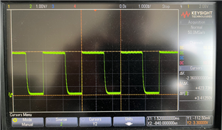
The signal is periodic, period time approx. 2.36ms. The voltage ranges between 0V and 3.3V.
My code looks like this:
/**
 * main.c
 */
#include "ti_msp_dl_config.h"

#define TIMER_CAPTURE_PERIOD (2000)

volatile bool gCheckDutyAndPeriod;

int main(void)
{
    volatile static uint32_t pwmPeriod;
       __attribute__((unused)) volatile static uint32_t pwmDuty;
       bool isSyncDone = false;

       SYSCFG_DL_init();

       NVIC_EnableIRQ(CAPTURE_0_INST_INT_IRQN);

       DL_TimerG_startCounter(CAPTURE_0_INST);

       DL_TimerG_startCounter(PWM_0_INST);

       while (1) {
           gCheckDutyAndPeriod = false;
           while (false == gCheckDutyAndPeriod) {
               __WFE();
           }

           /*
            * In Capture Combined Mode the timer is counter is reloaded every time
            * a rising edge is detected and capture compare register 0 loads the
            * counter value when the another rising edge is detected.
            * Therefore the period of the pwm signal will be the reload value
            * minus the capture compare register value.
            */
           pwmPeriod =
               TIMER_CAPTURE_PERIOD - (DL_Timer_getCaptureCompareValue(
                                          CAPTURE_0_INST, DL_TIMER_CC_1_INDEX));
           /*
            * In Capture Combined Mode the number of timer clocks that the signal
            * remained high is captured in capture compare register 1.
            * In  order to determine timer clocks between a rising edge and
            * the next falling edge. It is necessary to subtract the timer
            * reload value minus  capture compare register 1 value.
            *    t_high = TIMER_CAPTURE_PERIOD - TIMER_X_CC01[1]
            * To calculate the duty cycle use the following formula:
            *  pwmDuty = (t_high / pwmPeriod) * 100
            */
           pwmDuty = ((TIMER_CAPTURE_PERIOD -
                          DL_Timer_getCaptureCompareValue(
                              CAPTURE_0_INST, DL_TIMER_CC_0_INDEX)) *
                         100) /
                     pwmPeriod;

           if (isSyncDone) {
               /*
                * Set a breakpoint to inspect pwmPeriod and pwmDuty results */
               //__BKPT(0);
           } else {
               /*
                * More than one clock period must be captured to ensure that the
                * timers are synchronized.
                */
               isSyncDone = true;
           }

       }
}

void CAPTURE_0_INST_IRQHandler(void)
{
    switch (DL_TimerG_getPendingInterrupt(CAPTURE_0_INST)) {
        case DL_TIMERG_IIDX_CC0_DN:
            gCheckDutyAndPeriod = true;
            break;
        default:
            break;
    }
}
The .sysconfig -File for the Timer looks like this:
CAPTURE1.$name = "CAPTURE_0";
CAPTURE1.captMode = "COMBINED";
CAPTURE1.timerClkPrescale = 256;
CAPTURE1.interrupts = ["CC0_DN"];
CAPTURE1.timerPeriod = "16ms";
CAPTURE1.timerClkDiv = 8;
CAPTURE1.peripheral.$assign = "TIMA0";
CAPTURE1.peripheral.ccp0Pin.$assign = "PA0";
My problem is that the timer does not measure the period time correctly. The value I get for the variable "pwmPeriod" is always 1751(dec), no matter what frequency is applied to pin 1.
1751*(1/15630) = 11ms/period -> should be 2.36ms/period.
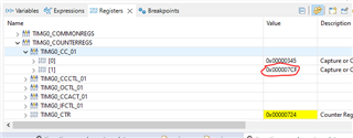
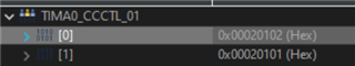
The value of register CC01 is always 0xF9.
The value of register CC00 is changing, depending on the high-time of the signal.
Does anyone know what I am doing wrong?