This thread has been locked.

If you have a related question, please click the "Ask a related question" button in the top right corner. The newly created question will be automatically linked to this question.

RM57L843: Low Power Oscillator and Clock Detect configuration

Part Number: RM57L843
Other Parts Discussed in Thread: HALCOGEN

Hello,

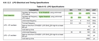
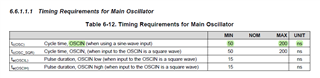
Considering this statement: 'The valid OSCIN frequency range is defined as: fCLK10M / 4 < fOSCIN < fCLK10M * 4.", is the "Low Power Oscillator and Clock Detect" capable of detecting variation of 50ppm?

Is the value of HF LPO related to the frequency of the crystal? In this video: www.ti.com/.../3871660449001, the crystal is 16MHz and PLL1 is 160MHz and the HF LPO is 10. If yes, what is the value to use in HALCoGEN to configure the HF LPO to the monitor the oscillator when the crystal is 16MHz and PLL1 is 300MHz?

Regards,
Marcio Borges.

  • Hi Marcio,

    fCLK10M / 4 < fOSCIN < fCLK10M * 4.", is the "Low Power Oscillator and Clock Detect" capable of detecting variation of 50ppm?

    No, this clock detection circuit cannot be helpful to detect the small variations.

    It can only be helpful as a crystal oscillator failure detection circuit.

    The above are the thresholds of the clock detection circuit, the typical lower threshold is 2.4Mhz(fCLK10M / 4) and typical higher threshold is 38.4Mhz(fCLK10M * 4).

    And the main oscillator frequency can be in between 5Mhz to 20Mhz right.

    So, what this clock detection circuit will do is, it will compare your OSCIN frequency with the lower threshold and higher threshold window. If your OSCIN frequency is with in this window, then its fine but if your oscillator frequency out of the window then this detection circuit will SET the GLBSTAT bit 0: OSC FAIL.

    I hope this clarifies your doubts.

    --

    Thanks & regards,
    Jagadish.