This thread has been locked.

If you have a related question, please click the "Ask a related question" button in the top right corner. The newly created question will be automatically linked to this question.

MSPM0L1304: Current sensing circuit of MSPM0.

Part Number: MSPM0L1304

Hi, 

Can the ADC on MSPM0 measure current with the circuit below?

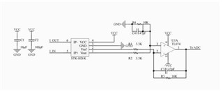
The positive input of the OPAMP is 2.5 V, and the negative input is from 0 to 5 V.

The ASCVRSEL will be set to 0 or 2.  (0h = VDDA reference. 2h = Internal reference.)

We can't use the EXTREF pin.


The current ranges from 0A to 80A.

Is there an app note or circuit related to the current measurement using M0?

Thanks.

  • Hello,

    Can I clarify with you about the inputs to the op amp?

    I was able to find this circuit through the datasheet for that current sensing part. From that datasheet, I see that the inverting (negative) input of the op amp and the non-inverting (positive) inputs of the op amp are switched from what you had mentioned above. 

    If this is the case, you may need to make some modifications to the circuit in order to get an acceptable range for voltage input into an MSPM0 ADC. With this circuit as-is, the voltage range looks to be between -7.5 and 7.5, which is not compatible. The acceptable range of input to an M0 ADC pin is between 0 V and whatever reference you want set (1.4, 2.5, or 3.3V). 

    I will look to see if we have any documentation available.

    Thanks,

    Greg

  • Hello,

    Thank you for your reply. 

    I made a mistake about the input of opamp.

    You're right.

    I'll wait for the document.

  • Hello,

    Thanks for confirming. I wanted to make sure before moving forward.

    Unfortunately, we do not have a readily available current sensing solution for M0 at this time, but we are working on getting a solution out in the near future that does use current sensing in it. You can feel free to double check the available technical documentation for M0 solutions. We also have some options provided by TI (under the current sensing section) that you can double check, but I don't see any that wouldn't need modifications due to the current range of your solution. 

    I did a little more digging into that datasheet for the current sensing part. There's a couple issues I see with its use.

    1.) You mentioned your solution requires a range between 0 and 80 amps, but I see that part only accommodates for sensing between -50 and 50 amps.

    2.) As mentioned before, the range for the above circuit would be between -7.5V and 7.5V. This instead needs to be between 0V and Vref_adc (the reference voltage for the M0 ADC). If you were to overcome the current range issue, you would be able to modify this circuit for adapting with the M0 by making 2 changes. Here's some insight on how I derived this.

    Using superposition, you can see that the equation for the voltage at the op-amp output: V = Vout*(10k/3.3k) - Vref*(10k/3.3k)

    where Vref is 2.5V and Vout is 0V to 5V. Since we don't need any kind of negative bias, you can simply route the Vref node to GND. You wouldn't even need to connect Vref from the part to the circuit in this case, and Vref would become 0V. The range after this change would be 0V to 15.15V. The second change needed would be a voltage divider at the output of the op amp to bring the voltage range down. You would need to pick resistors that create a voltage ratio of Vref_adc/15.15 (depends on what your ADC reference voltage chosen on the M0 is). Again, this is all assuming you can get past any current range issues with the chip. Feel free to double check the datasheet to see if I might have missed anything on that topic.

    Regards,

    Greg