This thread has been locked.

If you have a related question, please click the "Ask a related question" button in the top right corner. The newly created question will be automatically linked to this question.

TMDSEMU200-U: burning of U7 IC

Part Number: TMDSEMU200-U
Other Parts Discussed in Thread: TMS320F2812

Hi.. Experts,

Recently I had purchased XDS200 USB Emulator (INV 5930563619 Dt- 27 May 2023) from TI Web site.

I received the material on 16/06/2023 through DHL courier. The serial no. of product is TC57500

I started using it from the next day. We have custom CPU board for our CNC Controller based on TMS320F2812 processor.

We were using Spectrum Digital JTAG for our custom board from 2015.

Till 26/6/2023 we were using it for debugging & programming.

In between, some time I had Error 1156 of low power mode but after power on reset to board & JTAG , it was working properly.

On 27/06/2023 morning it stopped working by showing Error 183 - cable break error far from itself.

I contacted TI customer support as it was under warranty to understand problem & solution.

TI customer support confirm that it is cable break issue with description & possible check point.

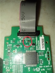
Being a cable break issue, I opened JTAG box to check continuity of FRC cable, when I saw a PCB component U7 is burnt down.  

I have attached picture of PCB. 

I am not sure why U7 burnt as particular CPU board design is properly tested & working since 2006 & we have been using Spectrum Digital, Blackhawk JTAG with this particular design for last 15 years and particular JTAG was also working from 16th to 26th June. 

TI Customer care earlier confirmed that it is warranty issue & suggested me to post query on TIE2E platform to understand possible cause. 

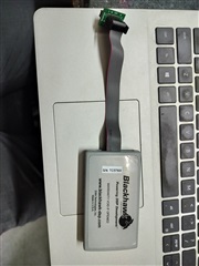
In between as this process was taking time, I purchased same Blackhawk JTAG(XDS200 USB Emulator ) from Mouser electronics as it was out of stock on TI web site and started working with it. It is working fine. 

Can experts from the TI E2E forum please let us know possible cause? OR it is manufacturing issue.  

Thanks & regards

Abhijit Kelkar

  • Hi,

    How are you able to determine that U7 is burnt down? 

    These boards are designed and manufactured by Blackhawk, so I am not sure how this happened or even what the U7 part is. I think you will have to reach out to them about this. 

    You only ever connected the XDS200 to your PC and the same target board that is functioning fine now? 

    Best Regards,

    Ben Collier

  • , since the product was purchased from TI store, the warranty claim would need to come through TI.

    Abhijit,

    In cases like these, we'd normally try to determine if the device was defective or if it was damaged during use. Would you please post a snapshot of the JTAG connector on your board, where the XDS200 is connected to? Just want to see if maybe there is an issue there that may end up damaging other debug probes. 

  • Hi.. Ben ,

    I think you have not seen the attached photo of JTAG PCB with my post. I am attaching it again. Component U7 is marked in red circle to locate easily. It is clearly visible as burnt down. I know these boards are designed and manufactured by Blackhawk but I have purchased it from TI web store. So naturally I will talk with TI for warranty claim.

    To answer second part of question, yes I connected XDS 200 to my Laptop & to same target board that is functioning fine now with XDS200 which I newly purchased from Mouser Electronics. Earlier I was working with same board as it is part of our company machine on which we regularly do the development.

    To clarify more, we have no. of ready board of the same design as we are manufacturer of these board & during period of 16/6/23 to 26/6/23, I connected particular burnt JTAG to different board for programming purpose. On 24th-26 th , I was working with the same development machine with this JTAG only. After 27th I have stop working as JTAG stopped working.

    Hope it answered your query. 

    Abhijit

  • Hi.. Gus,

    thanks for reply.

    As I mentioned in my earlier post, our custom designed CPU Card of our CNC Controller is not a new design. We are using this particular board in our CNC machine from 2006 onwards and there are more than 1500 such machines working in market. 

    We being a manufacturer of CNC Engraving machine, do continues R&D in our CNC controller & we have one such machine in our company where I was working. The board in particular R&D machine is also not new one, it was working with earlier Spectrum Digital XDS2000 series JTAG, which we were using from 2016. Prior to 2016 , we had Blackhawk JTAG for these boards.  

    So I do not see issue with the design. I also checked JTAG connector of particular R&D machine PCB for correctness of soldered component & it is OK. When I traced connections of burnt component U7 on JTAG board, I do not see any Power related pins coming to particular U7 component. I have attached traced connection diagram for your ready reference.

    I can send snapshot of JTAG connector on Monday due to weekend. I am also more worried about reason as JTAG is costly part and everything comes to standstill without JTAG.  

    Abhijit

    U7_Pinconnections_2.pdf

  • I can send snapshot of JTAG connector on Monday due to weekend.

    Just to be clear, I am looking for a schematic diagram of the JTAG connector on your board.

    I am also more worried about reason as JTAG is costly part and everything comes to standstill without JTAG.  

    This is what I would like to figure out. The Blackhawk XDS2000 is obviously from a different manufacturer then the Spectrum Digital XDS200. There will be some differences between both products. I would like to make sure you don't continue to face this issue in the future.

  •   

    Hi.. JTAG Schematic is attached. I was out of town so could not reply.

    thanks

    Abhijit

  • Abhijit,

    The image didn't come across clearly. Can you repost? 

  • Gus

    Sorry I missed your reply.

    Any way I have attached schematic diagram again. Just for clarification, Pin 4,8,10,12 connected to GND in net file. 

    Abhijit 

  • Only potential issue I see is that pin 5 (VTref) is connected to 5V whereas this would normally be connected to the MCU's 3.3 I/O supply through a 100 ohm resistor to limit the current. See "VTref considerations" in page below.

    https://dev.ti.com/tirex/explore/node?node=A__AOi9Jj0vmBMJ0KQKaKITgg__xdsdebugprobes__FUz-xrs__LATEST

    Also, see this note about Vtref: "Should be tied to the I/O voltage of the target device. Used to detect if power is active and to set JTAG signal voltage level translators if supported by the XDS(1)." You could be driving 5V back to the MCU I/Os. 

  • Hi.. Gus, 

    thanks for your reply.

    About PIN 5 ,

    1. As I have already mentioned in my earlier post, the particular PCB was designed in 2003-2004. In 2002-3 onwards, we were working with Spectrum Digital ezDSP kit for initial experimentation and while designed this PCB, naturally we followed ezDSP schematic. This design has Pin 5 tied to +5V supply and we copied the same system in our design. I am attaching ezdsp schematic & technical documentation for your reference. 

    2. We have been using various Spectrum Digital, Blackhawk JTAG models suitable for F2812 with this design & we did not have any issue. Our last JTAG was Spectrum C2000 series JTAG, which we were using for 4-5 years. The burned JTAG was also working with same boards for around 15 day. If it is power issue, then no 3.3v system can tolerate +5V for such long time.

    3. Particular component U7, which burnt down has no connection to PIN 5 of JTAG connector. The adjacent component U6 does have connection to PIN 5 but it is intact.  

    considering above points 2&3, I do not think it is +5V issue. It could be typical component failure as well.

    Abhijit


    2812_ezdsp_Schem_C.pdf2812_ezdsp_TechRef_D.pdf 

  • Hello Abhijit,

    I have received information from Blackhawk on these components. U7, U8,U6 are TI TPD4E002DRLR ESD protection devices.

    These devices can take a fair amount of ESD, so it's a bit puzzling why U7 would be damaged. Is the equipment handled with proper grounding to prevent/minimize ESD?

  • Hi.. Gus,

    Oh.. YES  it is VERY surprising & puzzling as well.

    Our machines Panel is having proper earth bus bar connection & Wiring. We have SOP for connecting our CNC machines to mains power supply. Earthing is very critical point in SOP & we always make separate earthing for the machine. CNC controller needs to communicate with Sevo Drives &Spindle (Inverter) Drive. Servo Drives and Spindle drive generate lot of noise & we need to maintain data integrity for tool path data. Small problem in tool path data integrity can result into accident.

    Naturally we have to take lot of care for Grounding & Power noise suppression like using shielded cable & Ferrite cores, Galvanic isolation in low side and high voltage side ground etc. Our panel is designed considering all these problems. 

    In this case also total panel is properly grounded and even today that machine is working in same fashion.  So, I really do not see any ESD related issue as well.

    One more observation I would like to tell you. 

    After this incident, when I was checking all possible conditions, I also noticed point of "5V connected to PIN 5" of JTAG connector so with slight PCB modifications I started using my new JTAG with 3.3V connected to Pin 5 through 100 ohm resistors. I made changes to all available PCBs. But many times, I get following error.

    [ERROR] C28xx: Trouble Reading Register PC: (Error -1156 @ 0xA) Device may be operating in low-power mode. Do you want to bring it out of this mode? Choose 'Yes' to force the device to wake up and retry the operation. Choose 'No' to retry the operation without waking the device.

    This error occurs mainly in debug mode. While debugging if I make small change in programs and reprogram the change then this error occurs after resetting. I then have to close CCS, power off the system, remove USB connector of JTAG and reconnect it laptop & start fresh debug session. 

    Some time same error occur while debugging program in F5/F6 mode.

    I am also not clear what is reason for the same. This is the first time in last 15 years I am observing this error and again I am getting this error with multiple modifiedboards and not to specific board.

    Regards

    Abhijit

  • Abhijit,

    In this case also total panel is properly grounded and even today that machine is working in same fashion.  So, I really do not see any ESD related issue as well.

    OK, I think it's clear the debug probe was defective and not damaged during use. You can go ahead and apply for an RMA and use this forum thread as proof issue was debugged if needed.

    I am also not clear what is reason for the same. This is the first time in last 15 years I am observing this error and again I am getting this error with multiple modifiedboards and not to specific board.

    This is strange indeed. I'm not sure what is happening. Please keep your original design and let me know if you have any further issue.