Part Number: TMS570LC4357
Hi Team,
1. When using the input TZ (tripzone) signal of the oscilloscope to capture, it is found that the glitch appears in multiple positions, and the interval between them is relatively large. Please refer to the diagram below. In this case, if the WINDOW filter interval is configured, the first glitch interval can be filtered, but the second glitch cannot be filtered (as shown in the WINDOW_1 interval in the figure below). If customer wants to filter, he can only use the WINDOW_2 method in the figure below to filter, but there are two problems:
1). WINDOW_2 will filter out the normal glitch-free interval in TZ (the area between the two glitches in the figure below)
2). The bit width of the dcfwindow register is 8 bits, and its width may not cover the entire interval where the two glitches appear.

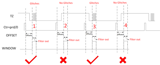
2. In some usage scenarios, it is found through oscilloscope measurement that the current TZ signal input is low for a long time, crossing the boundary of ctr=prd/0, and occurs periodically. The details are shown in the figure below. At this time, the glitch at position 1 in the figure below can be filtered by setting the dcfoffset and dcfwindow registers. But at position 2, the same dcfoffset and dcfwindow parameters will still be valid, resulting in that when there is no glitch on the TZ at position 2 in the figure, it will also be filtered out.
1). What should be the normal configuration process of the software?
2). Let the software make dcfoffset and dcfwindow take effect once at an interval of ctr=prd/0 to filter the position where glitches should appear?
3). Does the value of the dccap register read at this time make sense?
Regards,
Annie