This thread has been locked.

If you have a related question, please click the "Ask a related question" button in the top right corner. The newly created question will be automatically linked to this question.

MSPM0L1306: I2C target device hot swap (plug and play) issue

Part Number: MSPM0L1306

Hi there,

We are designing a device (fuel gauge) using MSPM0L1306 controller, and set the I2C0 in target mode, using PA0 & PA1 pins (which don't have internal pull-up resistors, for 5v tolerant). We don't deploy pull-up resistors on the target (self) side, the pull-up resistor is only present on the host side (to fit any resonible IO voltage).

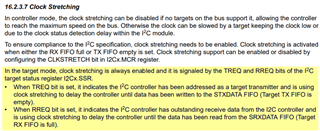
We observed that if clock stretching is enabled, the SCL pin will be hold low permanently by MSPM0L1306. This prevent our host side to communicate with target, and block the further functionality.

Do you know how can we design a mechanism to let MSPM0L1306 distinguish the target disconnection from host device (pull-up resistor disappear)? And recover the communication once it plugged to host device (with correct pull-up resistors)?

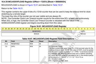
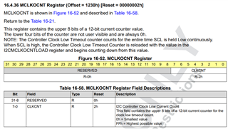
Also, in reference manual 16.2.3.6, the register name I2Cx.MCLKOCNTLOAD doesn't exist in the later I2c registers chapter. Maybe another name? (manual typo)

Bests,

  • Hello Tiger,

    I'm looking at the TRM now, and according to it, when in I2C Target mode, Clock stretching is always enabled.  So, what do you mean when you say "if clock stretching is enabled"?  I'm guessing if the I2C is hanging, than it may somehow be related to these TREQ or RREQ bits, when the I2C module thinks it's in the middle of a transmission/reception.  

    Currently, I'm thinking we just need some sort of timeout and to re-initialize the I2C module.  If there is a timeout, we could also then set an interrupt on the PA0 edge when it's plugged in, and then know when to re-configure the I2C module.  

    As for the MCLKOCNTLOAD register, it seems to be for the Controller side only.  You are correct that the register definition appears to be missing, which I believe is just a document mistake.  I'll link it below from the Pre-production datasheet for reference, and I'll follow up with my Systems team to confirm this was purely accidently and have it fixed.  

    Thanks,

    JD

  • Hi JD,

    Thanks for the answer. However, I don't agree with your statement "In the target mode, clock stretching is always enabled...".

    I see in the latest TRM, the register description has that field.

    I also see following function in the most recent SDK (1.10.00.05):

    __STATIC_INLINE void DL_I2C_disableTargetClockStretching(I2C_Regs *i2c)
    {
        i2c->SLAVE.SCTR &= ~(I2C_SCTR_SCLKSTRETCH_MASK);
    }

    And if I invoke it to initialize the I2C, the problem disappear.

    Further more, on my end, if I pull the register I2C0->SLAVE.SSR and I2C0->CPU_INT.RIS regularly and print their values, I don't see significant change while the pull-up resistors are disappeared on SCL/SDA pins. However, at the same time, the SCL pin is struck at low forever and cannot be released, so block further communication.

    Again, repeat my questions:

    1. We will use I2C0 in target mode on PA0 & PA1, how should we distinguish remote device is removed (pull-up resistor disappear), and get ready upon remote device is recovered (pull-up resistors are connected)?
    2. Should we deploy (external) pull-down resistors on SCL & SDA pins to avoid them floating?
  • Hey Tiger,

    Thanks for pointing out the SCTR.SCLKSTRETCH bit.  I see the TRM should read that clock stretching is "enabled by default" instead of "always" enabled.  I've submitted that feedback already. 

    As for the I2C behaviour, I'm really not sure how it's expected to behave when the SDA/SCL pull-ups are removed or if that looks like a START condition or something to the MCU. 

    In your application, this disconnection can happen anytime, even mid-transaction, right?  When seeing the issue, is it at all related to when the disconnection happens in relation to the communication?  I imagine with clock-stretching enabled, the I2C bus spends much more time mid-transaction than when clock-stretching is disabled.  

    When connected, how often are there I2C transactions?  Or, what's the longest time you'd expect between them? 

    1. We will use I2C0 in target mode on PA0 & PA1, how should we distinguish remote device is removed (pull-up resistor disappear), and get ready upon remote device is recovered (pull-up resistors are connected)?
      1. [JD]  I still think a timeout is the best way to determine whether the remote Controller has been removed.  The easiest way to do this might be to use the EVENT publisher system to connect a Timer load to an I2C interrupt flag, so it gets automatically re-loaded every transaction.  Then, when we've timed out, we can check the SDA/SCL states and disable the I2C module.  
      2. For detecting the return of the remote controller, it would probably be best to reconfigure the pin as a GPIO and just interrupt on an edge.  Then we can re-init the I2C module and the pin.  
    1. Should we deploy (external) pull-down resistors on SCL & SDA pins to avoid them floating?
      1. [JD] I do believe this would probably also fix the issue.

    Thanks,

    JD

  • Thanks JD.

    In our use case, the disconnection can happen at ANY TIME, even during the I2C communication, or bus idle.

    I followed your suggestions, enabled the internal pull-down resistor (~40K from datasheet) all the time. I setup following state machines:

    1. The pins are configured as I2C target function. Reset, power up and configure I2c module with normal interrupts as needed. Configure timeoutA to detect SCL low timeout (0xFF)
      1. We regularly check I2C0->CPU_INT.RIS & DL_I2C_INTERRUPT_TIMEOUT_A condition (in main() loop, do not use interrupt), and if it happens, we turn-off I2C related interrupts, power off I2C module, and move to next state
    2. The pins (SCL/SDA) are configured as GPIO input, enable rising edge interrupt to detect host device connection.
      1. Upon the interrupt happens, disable the GPIO function (and interrupt), and
      2. move to next state (start over, from 1)

    However, the above state machine only work once (1 -> 2 -> 1). We cannot get state transition from 1->2 again. The RIS register is always 0x00080000, even the SCL is tied low. (multimeter tested, pin shorted to ground, ~40Ohm).

    BTW, we haven't change the clock stretching setting (enable by default for target).

    Can you point out why we cannot get the timeoutA flag set at 2nd time?

  • Hey Tiger,

    I'm not sure why it's working the first time but not the second.  Are you using the exact same I2C initialization function as the first time?  Can you share how you're shutting down the I2C module and how you're re-initializing it?

    On the 2nd loop, can you check the TIMEOUT_CTL register and maybe also TIMEOUT_CNT.TCNTA to see the current Timeout count is?

    Honestly, I haven't personally used the I2C's built-in timeout feature before and I wasn't sure it would work since it's technically on the "controller" side of the I2C Module.  I was actually suggesting setting up a external timeout using either TIMGx or the WWDT timer and to just re-load it every periodic I2C Interrupt.  Wouldn't matter what it is, even it was just an RX complete ISR or FIFO interrupt.  Instead of monitoring the SCL line directly, we could just adjust the timer so when a transaction doesn't happen in X amount of time to trigger an interrupt or set an ISR flag. 

    Do you have a TIMGx or the WWDT to spare?  Or maybe we can tap into an existing one?  

    If you don't and we have to get this I2C Timeout timer working, let me know, and I'll help dig further.   

    Thanks,

    JD


  • Hi JD,

    I think in the most recent TRM, the description get mess between controller and target.

    • Keyword "timeout check" under SMBUS.
    • 16.2.3.6 Clock Low Timeout (CLKTO), register map has changes between 0.57.00.00 and 1.10.00.05. I am not sure whether IC has changed in this part, it seems the description on the TRM doesn't reflect the up-to-date SDK.
      • 0.57.00.00 I2Cx->MASTER.MCLKOCNT & I2Cx->MASTER.MCLKOCNTLOAD (same address is reserved in newer version)
      • 1.10.00.05 I2Cx->TIMEOUT_CTL & I2Cx->TIMEOUT_CNT (same address was reserved in older version)
      • If I pull the old address (reserved) on production IC & SDK, result always 0.
      • Why the registers moved out of "MASTER" register group? Does it indicate both of controller (master) and target (slave) will have this timeout feature?

    I think regularly check the I2C communication is not feasible, since we cannot guarantee that host device regularly communicate with target device.

    Simplified code attached.

    #include <ti/driverlib/driverlib.h>
    #include <ti/driverlib/m0p/dl_core.h>
    
    #define POWER_STARTUP_DELAY                                                (16)
    /* Definitions for I2C external*/
    #define I2C_INST_EXT                                                      (I2C0)
    #define I2C_INST_EXT_INT_IRQN                                    (I2C0_INT_IRQn)
    #define I2C_INST_EXT_CLOCK_SOURCE                          (DL_I2C_CLOCK_BUSCLK)
    #define I2C_INST_EXT_TARGET_ADDRESS                                       (0x55)
    /* GPIO configuration - I2C external */
    #define GPIO_I2C_EXT_PORT                                                (GPIOA)
    #define GPIO_I2C_EXT_INT_IRQN                                   (GPIOA_INT_IRQn)
    #define GPIO_I2C_EXT_SDA_PIN                                     (DL_GPIO_PIN_0)
    #define GPIO_I2C_EXT_SDA_EDGE                          (DL_GPIO_PIN_0_EDGE_RISE)
    #define GPIO_I2C_EXT_SCL_PIN                                     (DL_GPIO_PIN_1)
    #define GPIO_I2C_EXT_SCL_EDGE                          (DL_GPIO_PIN_1_EDGE_RISE)
    #define GPIO_IOMUX_I2C_EXT_SDA                                    (IOMUX_PINCM1) //PA0, pin 24
    #define GPIO_IOMUX_I2C_EXT_SDA_FUNCTION               (IOMUX_PINCM1_PF_I2C0_SDA)
    #define GPIO_IOMUX_I2C_EXT_SDA_ALTERNATE_FUNCTION  (IOMUX_PINCM1_PF_GPIOA_DIO00)
    #define GPIO_IOMUX_I2C_EXT_SCL                                    (IOMUX_PINCM2) //PA1, pin 1
    #define GPIO_IOMUX_I2C_EXT_SCL_FUNCTION               (IOMUX_PINCM2_PF_I2C0_SCL)
    #define GPIO_IOMUX_I2C_EXT_SCL_ALTERNATE_FUNCTION  (IOMUX_PINCM2_PF_GPIOA_DIO01)
    
    void msp_i2c_target_wait_host_deinit(void) {
        NVIC_DisableIRQ(I2C_INST_EXT_INT_IRQN);
        NVIC_ClearPendingIRQ(GPIO_I2C_EXT_INT_IRQN);
        DL_GPIO_clearInterruptStatus(GPIOA, GPIO_I2C_EXT_SDA_PIN | GPIO_I2C_EXT_SCL_PIN);
        DL_GPIO_disableInterrupt(GPIOA, GPIO_I2C_EXT_SDA_PIN | GPIO_I2C_EXT_SCL_PIN);
    }
    
    void msp_i2c_target_wait_host_init(void) {
        /* Enable module */
        DL_GPIO_initPeripheralInputFunction(
            GPIO_IOMUX_I2C_EXT_SDA, GPIO_IOMUX_I2C_EXT_SDA_ALTERNATE_FUNCTION |
            IOMUX_PINCM_INV_DISABLE | IOMUX_PINCM_PIPU_DISABLE |
            IOMUX_PINCM_PIPD_ENABLE | IOMUX_PINCM_HYSTEN_DISABLE |
            IOMUX_PINCM_HIZ1_ENABLE | IOMUX_PINCM_WUEN_DISABLE);
        DL_GPIO_initPeripheralInputFunction(
            GPIO_IOMUX_I2C_EXT_SCL, GPIO_IOMUX_I2C_EXT_SCL_ALTERNATE_FUNCTION |
            IOMUX_PINCM_INV_DISABLE | IOMUX_PINCM_PIPU_DISABLE |
            IOMUX_PINCM_PIPD_ENABLE | IOMUX_PINCM_HYSTEN_DISABLE |
            IOMUX_PINCM_HIZ1_ENABLE | IOMUX_PINCM_WUEN_DISABLE);
        DL_GPIO_setLowerPinsPolarity(GPIOA, GPIO_I2C_EXT_SDA_EDGE | GPIO_I2C_EXT_SCL_EDGE);
        DL_GPIO_enableInterrupt(GPIOA, GPIO_I2C_EXT_SDA_PIN | GPIO_I2C_EXT_SCL_PIN);
        /* Initialize interrupts in NVIC */
        NVIC_ClearPendingIRQ(GPIO_I2C_EXT_INT_IRQN);
        NVIC_EnableIRQ(GPIO_I2C_EXT_INT_IRQN);
    }
    
    void msp_i2c_target_deinit(void) {
        NVIC_DisableIRQ(I2C_INST_EXT_INT_IRQN);
        NVIC_ClearPendingIRQ(I2C_INST_EXT_INT_IRQN);
        // DL_I2C_clearInterruptStatus(I2C_INST_EXT, 0xFFFFFFFF);
        DL_I2C_disableTimeoutA(I2C_INST_EXT);
        DL_I2C_disableTarget(I2C_INST_EXT);
        DL_I2C_disablePower(I2C_INST_EXT);
    }
    
    void msp_i2c_target_init(void) {
        /* Initialize I2C_EXT pins */
        DL_GPIO_initPeripheralInputFunction(
            GPIO_IOMUX_I2C_EXT_SDA, GPIO_IOMUX_I2C_EXT_SDA_FUNCTION |
            IOMUX_PINCM_INV_DISABLE | IOMUX_PINCM_PIPU_DISABLE |
            IOMUX_PINCM_PIPD_ENABLE | IOMUX_PINCM_HYSTEN_DISABLE |
            IOMUX_PINCM_HIZ1_ENABLE | IOMUX_PINCM_WUEN_DISABLE);
        DL_GPIO_initPeripheralInputFunction(
            GPIO_IOMUX_I2C_EXT_SCL, GPIO_IOMUX_I2C_EXT_SCL_FUNCTION |
            IOMUX_PINCM_INV_DISABLE | IOMUX_PINCM_PIPU_DISABLE |
            IOMUX_PINCM_PIPD_ENABLE | IOMUX_PINCM_HYSTEN_DISABLE |
            IOMUX_PINCM_HIZ1_ENABLE | IOMUX_PINCM_WUEN_DISABLE);
    
        /* Reset and enable power to peripheral */
        DL_I2C_reset(I2C_INST_EXT);
        DL_I2C_enablePower(I2C_INST_EXT);
        delay_cycles(POWER_STARTUP_DELAY);
    
        DL_I2C_setClockConfig(
            I2C_INST_EXT,
            (DL_I2C_ClockConfig *) &gI2C_INSTClockConfig);
        // DL_I2C_selectClockSource(I2C_INST_EXT, I2C_INST_EXT_CLOCK_SOURCE);
    
        /* Initialize I2C target */
        DL_I2C_disableAnalogGlitchFilter(I2C_INST_EXT);
    
        /* Configure Target Mode */
        DL_I2C_setTargetOwnAddress(I2C_INST_EXT, I2C_INST_EXT_TARGET_ADDRESS);
        DL_I2C_setTargetTXFIFOThreshold(I2C_INST_EXT, DL_I2C_TX_FIFO_LEVEL_BYTES_1);
        DL_I2C_setTargetRXFIFOThreshold(I2C_INST_EXT, DL_I2C_RX_FIFO_LEVEL_BYTES_1);
        DL_I2C_enableTargetTXEmptyOnTXRequest(I2C_INST_EXT);
    
        // DL_I2C_disableTargetClockStretching(I2C_INST_EXT);   //FIXME: might need in future. Currently it does not work with host system
    
        DL_I2C_setTimeoutACount(I2C_INST_EXT, 0xFF);
        DL_I2C_enableTimeoutA(I2C_INST_EXT);
    
        /* Configure Interrupts */
        DL_I2C_enableInterrupt(I2C_INST_EXT,
                            //    DL_I2C_INTERRUPT_TIMEOUT_A |
                               DL_I2C_INTERRUPT_TARGET_RXFIFO_TRIGGER |
                               DL_I2C_INTERRUPT_TARGET_START |
                               DL_I2C_INTERRUPT_TARGET_STOP);
    
        /* Enable module */
        DL_I2C_enableTarget(I2C_INST_EXT);
        // uint8_t data_dummy = 0;
        // DL_I2C_fillTargetTXFIFO(I2C0, &data_dummy, 1);
        // DL_I2C_flushTargetTXFIFO(I2C0);
    
        /* Initialize interrupts in NVIC */
        NVIC_ClearPendingIRQ(I2C_INST_EXT_INT_IRQN);
        NVIC_EnableIRQ(I2C_INST_EXT_INT_IRQN);
    }
    
    int main(){
        while (1) {
            DEBUG_PRINTLN_DEFAULT("I2C0 SSR: 0x%08x, raw RIS: 0x%08x",
                                    I2C0->SLAVE.SSR, I2C0->CPU_INT.RIS);
            DEBUG_PRINTLN_DEFAULT("I2C0 timeout countA: 0x%02x, timeout countB: 0x%02x",
                                    (I2C0->TIMEOUT_CNT) & 0xFF, (I2C0->TIMEOUT_CNT >> 16) & 0xFF);
            DEBUG_PRINTLN_DEFAULT("I2C0 timeout CTLA: 0x%04x, timeout CTLB: 0x%04x",
                                    (I2C0->TIMEOUT_CTL) & 0xFFFF, (I2C0->TIMEOUT_CTL >> 16) & 0xFFFF);
            DEBUG_PRINTLN_DEFAULT("OLD-I2C0 timeout count: 0x%08x, timeout control: 0x%08x",
                                    I2C0->MASTER.RESERVED0[0], I2C0->MASTER.RESERVED0[1]);
    
            // if(I2C0->SLAVE.SSR & DL_I2C_TARGET_STATUS_BUS_BUSY){
            //     static uint8_t busy_count = 0;
            //     busy_count++;
            //     if(busy_count > 5){
            //         busy_count = 0;
            //         DEBUG_PRINTLN_DEFAULT("I2C target busy timeout");
            //         msp_i2c_target_init();
            //     }
            // }
            // if(I2C0->CPU_INT.RIS & DL_I2C_INTERRUPT_TARGET_TXFIFO_TRIGGER){
            //     static uint8_t tx_fifo_trigger = 0;
            //     tx_fifo_trigger++;
            //     if(tx_fifo_trigger > 5){
            //         tx_fifo_trigger = 0;
            //         DEBUG_PRINTLN_DEFAULT("\tI2C tx trigger");
            //         uint8_t data_dummy = 0;
            //         DL_I2C_fillTargetTXFIFO(I2C0, &data_dummy, 1);
            //         DL_I2C_flushTargetTXFIFO(I2C0);
            //     }
            // }
            if(I2C0->CPU_INT.RIS & DL_I2C_INTERRUPT_TIMEOUT_A) {
                DL_I2C_clearInterruptStatus(I2C0, DL_I2C_INTERRUPT_TIMEOUT_A);
                printf("\tdeinit i2c, init gpio interrupt");
                msp_i2c_target_deinit();
                msp_i2c_target_wait_host_init();
            }
            delay_cycles(32000000);
        }
    }
    
    
    // shared interrupt handler for COMP0 and GPIOA
    void GROUP1_IRQHandler(void) {
        const uint32_t val = DL_Interrupt_getPendingGroup(DL_INTERRUPT_GROUP_1);
        printf("\t\tGROUP1 INT: %u (0x%08x)", val, val);
        switch (val) {
            case DL_INTERRUPT_GROUP1_IIDX_GPIOA:
                printf("\tdeinit gpio interrupt, init i2c");
                msp_i2c_target_wait_host_deinit();
                msp_i2c_target_init();
                break;
            case DL_INTERRUPT_GROUP1_IIDX_COMP0:
                break;
            default:
                break;
        }
    }
    
    
    bool dataRx = false;
    static bool rec_val = false;
    bool first_run = false;
    void I2C0_IRQHandler(void) {
        const DL_I2C_IIDX val = DL_I2C_getPendingInterrupt(I2C0);
        printf("\t\tI2C INT: %u (0x%08x)", val, val);
        switch (val) {
            case DL_I2C_IIDX_TARGET_START:
                /* Initialize RX or TX after Start condition is received */
                if (dataRx) {
                    DL_I2C_flushTargetTXFIFO(I2C0);
                    dataRx = false;
                }
                break;
            case DL_I2C_IIDX_TARGET_RXFIFO_TRIGGER:
                rec_val = true;
                {
                    /* Store received data in buffer */
                    dataRx = true;
                    while (DL_I2C_isTargetRXFIFOEmpty(I2C0) != true) {
                        bq27220_rx_byte(DL_I2C_receiveTargetData(I2C0));
                    }
                }
                break;
            case DL_I2C_IIDX_TARGET_TXFIFO_TRIGGER:
                rec_val = true;
                if (!first_run) {
                    first_run = true;
                    while (DL_I2C_transmitTargetDataCheck(I2C0, 0x00) != false)
                        ;
                } else {
                }
                break;
            case DL_I2C_IIDX_TARGET_STOP:
                //MSPM0L130x errata I2C_ERR_01
                if (!rec_val) {
                    uint8_t data_dummy = 0;
                    DL_I2C_fillTargetTXFIFO(I2C0, &data_dummy, 1);
                }
                rec_val = false;
                DL_I2C_flushTargetTXFIFO(I2C0);
    
                break;
            case DL_I2C_IIDX_TIMEOUT_A:
                //no used, poll in main
                // printf("\tdeinit i2c, init gpio interrupt");
                // msp_i2c_target_deinit();
                // msp_i2c_target_wait_host_init();
                break;
            case DL_I2C_IIDX_TARGET_RX_DONE:
            /* Not used for this example */
            case DL_I2C_IIDX_TARGET_RXFIFO_FULL:
            /* Not used for this example */
            case DL_I2C_IIDX_TARGET_GENERAL_CALL:
            /* Not used for this example */
            case DL_I2C_IIDX_TARGET_EVENT1_DMA_DONE:
            /* Not used for this example */
            case DL_I2C_IIDX_TARGET_EVENT2_DMA_DONE:
            /* Not used for this example */
            default:
                break;
        }
    }
    

  • Hey Tiger,

    Thanks for sharing the simplified code.  I was not able to review it yet, but I'll do my best to review it later tonight or first thing tomorrow.  

    Thanks,

    JD

  • I have an related question, if target STXFIFOTRG bit is set, and will the interrupt flag get cleared by doing nothing? (entering and, exiting the interrupt routine without filling the TXFIFO or explicitly clear the flag), will the interrupt get generated again?
    I observed some cases, same interrupt keep happening while we are dealing it in ISR code. For example, we have SRXFIFOTRG interrupt, when we read the from RXFIFO, STXFIFOTRG happens before we exiting the ISR routine. The SCL pin get struck due to STXFIFOTRG bit is set and target is waiting for filling the TXFIFO. However, the ISR didn't enter, so we cannot execute the TXFIFO filling code.

  • Hey Tiger,

    Just following up here.  I didn't look into this exact bit yet, but it sounded like on the sync earlier this week that you and the team got everything working.  

    Is that the case or is this question or other questions still open?  

    Thanks,

    JD