This thread has been locked.

If you have a related question, please click the "Ask a related question" button in the top right corner. The newly created question will be automatically linked to this question.

MCU-PLUS-SDK-AM243X: CPSW LWIP Example on Core RF0-1: UDMA RX Channel open fail

Part Number: MCU-PLUS-SDK-AM243X

Hello Experts,

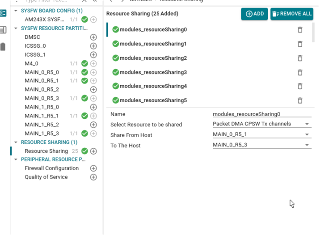
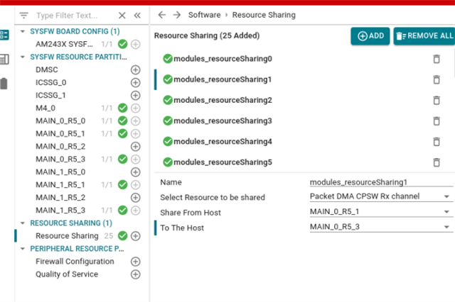
i'm trying to use the CPSW LWIP example on the HSFS Evaluation Board with SDK Version 08.06.00.43. It is working fine for Core 0-0 but on the Core 0-1 Version i always get the error that the UDMA RX Channel open failed. The specific code line is 1026 in cpsw.c: hCpsw->hRxRsvdFlow != NULL.

Could you help me figure out why this example won't run?

Regards

Robin

  • Hi Robin,
      Thanks for the post. Hope you are doing well!

    In order to achieve run CPSW example on R5F core 0_1, we need to change the configuration Resource Manager(RM) Tool to allow R5F to allocate a UDMA channel.
    I will come back to you with the complete instructions in a day.

    Thanks and regards,

    Pradeep

  • Hello Pradeep,
    thank you for your answer. I'm doing good, hope you are too! Instructions would definitely help me achieve this change, so I'm waiting on your reply.

    Regards

    Robin

  • Hi Robin,

    Please refer to https://software-dl.ti.com/mcu-plus-sdk/esd/AM243X/latest/exports/docs/api_guide_am243x/RESOURCE_ALLOCATION_GUIDE.html to know on how to open Resource Manager tool.

    We want to change CPSW TX and Rx Channels sharing between MAIN_0_R5_1 (R5F0_0 non-secure) and MAIN_0_R5_3 (R5F0_1 non-secure).

    In the tool,
    1. Go to MAIN_0_R5_0 : set CPSW Tx Ch Count = 0 and CPSW Rx Ch Count = 0.

    2. Go to MAIN_0_R5_1 : set CPSW Tx Ch Count = 9 and CPSW Rx Ch Count = 1.

    3. Go to 'Resource Sharing' : 

    - Change modules_resourceSharing0 as :

    - Change modules_resourceSharing1 as :

    4. Close Resource Manager Tool. Rebuild SBL as per steps mentioned here.

    5. Change board boot mode to UART boot mode and upload the newly build SBL to board as per the instructions mentioned in 'Flash SOC Initialization Binary'.

    6. Change board boot mode back to normal application load mode (either QSPI or NO_BOOT MODE) Recompile the example and rerun the example.

    Hope this helps. Let me know if you face any issues.

    With regards,

    Pradeep

  • Hello Pradeep,

    thank you for your instructions. I did as you said (only on step 2 i could only give 8 tx channels to main_0_1).
    I am getting different errors now, can you help me figure out a fix? Maybe there is more ressource allocation change necessary for the udma ring.

    edit: I changed the rings for cpsw tx and rx channel aswell and now it's working, thanks for your help

    Regards,

    Robin