


Part Number: TM4C123GH6PM
Other Parts Discussed in Thread: EK-TM4C123GXL, UNIFLASH
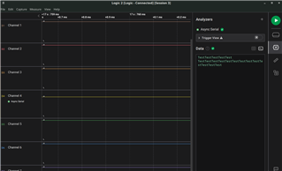
I am trying to interface Tiva C with FTDI using UART. I am able to send data from Tiva and receive in FTDI, but unable to read data in Tiva from FTDI. I am using below configuration:
115200 bps, 8 data bits, 1 stop bit, no parity
My hardware connections are:
TX (FTDI), with RX - PC4 (Tiva)
RX (FTDI), with TX - PC5 (Tiva)
ground pins of both connected to each other.
I have tested FTDI with ESP32 using UART, and it works. Please help me resolve the issue. I have attached code in case of misconfigured software.#include <string.h>
#include "color_generator.h"
#include "inc/hw_ints.h"
#include "driverlib/uart.h"
#include "driverlib/interrupt.h"
#define MAX_SIZE 17
#define BAUD_RATE 115200
#define DELAY 50000000
char received_message[MAX_SIZE];
uint8_t loop_var = 0;
uint32_t len = 0;
const char* messages[] = {"WiFi started", "HTTP started", "WiFi connected"};
const char* text = "Received message: ";
const char* clear_screen = "\033[2J";
const char* newline_carriage_return = "\n\r";
const char* acknowledgement = "Indicating status...";
void uart_setup()
{
// enable interrupts
IntEnable(INT_UART4_TM4C123);
// logging
// enable gpio port A
SysCtlPeripheralEnable(SYSCTL_PERIPH_GPIOA);
while (!SysCtlPeripheralReady(SYSCTL_PERIPH_GPIOA))
{
// wait till peripheral is ready
}
GPIOPinConfigure(GPIO_PA0_U0RX | GPIO_PA1_U0TX);
GPIOPinTypeUART(GPIO_PORTA_BASE, GPIO_PIN_0 | GPIO_PIN_1);
// enable UART0
SysCtlPeripheralEnable(SYSCTL_PERIPH_UART0);
while (!SysCtlPeripheralReady(SYSCTL_PERIPH_UART0))
{
// wait till peripheral is ready
}
UARTConfigSetExpClk(UART0_BASE, SysCtlClockGet(), BAUD_RATE, UART_CONFIG_WLEN_8 | UART_CONFIG_STOP_ONE | UART_CONFIG_PAR_NONE);
UARTEnable(UART0_BASE);
// communication with FTDI
// enable gpio port C
SysCtlPeripheralEnable(SYSCTL_PERIPH_GPIOC);
while (!SysCtlPeripheralReady(SYSCTL_PERIPH_GPIOC))
{
// wait till peripheral is ready
}
GPIOPinConfigure(GPIO_PC4_U4RX | GPIO_PC5_U4TX);
GPIOPinTypeUART(GPIO_PORTC_BASE, GPIO_PIN_4 | GPIO_PIN_5);
// enable UART4
SysCtlPeripheralEnable(SYSCTL_PERIPH_UART4);
while (!SysCtlPeripheralReady(SYSCTL_PERIPH_UART4))
{
// wait till peripheral is ready
}
UARTIntEnable(UART4_BASE, UART_INT_RT);
// UARTLoopbackEnable(UART4_BASE);
UARTConfigSetExpClk(UART4_BASE, SysCtlClockGet(), BAUD_RATE, UART_CONFIG_WLEN_8 | UART_CONFIG_STOP_ONE | UART_CONFIG_PAR_NONE);
UARTEnable(UART4_BASE);
}
void debug_led()
{
SysCtlPeripheralEnable(SYSCTL_PERIPH_GPIOF);
while (!SysCtlPeripheralReady(SYSCTL_PERIPH_GPIOF))
{
// wait till peripheral is ready
}
GPIOPinTypeGPIOOutput(GPIO_PORTF_BASE, GPIO_PIN_1 | GPIO_PIN_2 | GPIO_PIN_3);
GPIOPinWrite(GPIO_PORTF_BASE, GPIO_PIN_1 | GPIO_PIN_2 | GPIO_PIN_3, 0);
}
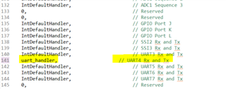
void uart_handler()
{
UARTIntClear(UART4_BASE, UART_INT_RT);
loop_var = 0;
while (UARTCharsAvail(UART4_BASE) && loop_var < MAX_SIZE)
{
// GPIOPinWrite(GPIO_PORTF_BASE, GPIO_PIN_1, GPIO_PIN_1);
int32_t ch = UARTCharGet(UART4_BASE);
// log_to_uart(&ch);
received_message[loop_var] = ch;
loop_var++;
}
// write received text to console
log_to_uart(newline_carriage_return);
log_to_uart(text);
// GPIOPinWrite(GPIO_PORTF_BASE, GPIO_PIN_1, GPIO_PIN_1);
log_to_uart(received_message);
write_to_uart(acknowledgement);
}
void write_to_uart(const char* text)
{
len = strlen(text);
for (loop_var = 0; loop_var < len; loop_var++)
{
UARTCharPut(UART4_BASE, text[loop_var]);
while (UARTBusy(UART4_BASE))
{
// wait till transmit FIFO is empty
}
}
}
void log_to_uart(const char* text)
{
len = strlen(text);
for (loop_var = 0; loop_var < len; loop_var++)
{
UARTCharPut(UART0_BASE, text[loop_var]);
while (UARTBusy(UART0_BASE))
{
// wait till transmit FIFO is empty
}
}
}
int main(int argc, char const *argv[])
{
// set system clock frequency to 16 MHz
SysCtlClockSet(SYSCTL_USE_OSC | SYSCTL_OSC_MAIN | SYSCTL_XTAL_16MHZ);
// setup
uart_setup();
log_to_uart(clear_screen);
debug_led(); // debug
while (true)
{
// listen for input
// write_to_uart("loopback");
// SysCtlDelay(DELAY);
}
return 0;
}


 wrong with my code or otherwise.
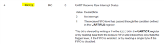
 :
: