This thread has been locked.

If you have a related question, please click the "Ask a related question" button in the top right corner. The newly created question will be automatically linked to this question.

TM4C123GH6PM: MCU can't be flashed while the VDDC value is OK

Part Number: TM4C123GH6PM

Hello

I have a TM4C123GH6PM can't be flashed over the In-Circuit Debug Interface (ICDI) with CCS, but when we  check the VDDC level is OK 1.2V which lead us to assume that MCU core is OK too, would you please advise, is there any way to find out healthiness of MCU and how it's flashing problem can be solved?

BR

Hani

  • Hi Hani,

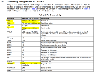
      Is this a LaunchPad board with TM4C123GH6PM  on it or you have your custom board? I assume you have your own custom board and you are intending to use the ICDI on a LaunchPad to debug/program your custom board. If this is the case, please follow section 4.6 in this app note. https://www.ti.com/lit/pdf/spma075. Please also follow section 6 to debug any connection and flashing issue. 

      Use the app note to make sure you follow the recommended JTAG port design such as pullup resistors on JTAG pins. Also check for proper connections between the ICDI and your custom board according to section 4.6. 

  • dear  

    we have made many custom boards and we are able to connect & debug the MCU, but we have Qty(2) boards we are not able to debug so we are sure that our design & In-Circuit Debug Interface (ICDI) functioning well, also we have a doubt that MCU core is OK because we can measure 1.2 V for the VDDC, our question is how can we make sure if the MCU is OK of HW failed?

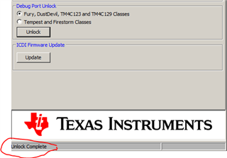
    Note: the LM flash programmer can unlock the debug ports successfully as shown below

    BR

  • our question is how can we make sure if the MCU is OK of HW failed?

    Hi Hani,

      The best way to find out is to do a ABA swap test. You said you have many of the custom boards working. With that you can perform a ABA swap to isolate if the problem is MCU or your board. 

    The A-B-A Swap Method is a simple cross check test, which can confirm the observed issue is not systemic.

    • A-B-A Swap Method
      (1) Remove the suspected component (A) from the original failing board.
      (2) Replace the suspected component (A) with a known good component (B) and check if the original board now works properly.
      (3) Mount the suspected component (A) to a known good board and see if the same faliure occurs on the good board.

    Step 3 is important because it helps us to exclude any possibility that the issue is caused by a systemic issue or the interaction of multiple slightly bad components on a good board.

    we have made many custom boards and we are able to connect & debug the MCU,

    I'm curious as to how you implement the ICDI on your custom board. Can you please elaborate? Do you use a LaunchPad board which has a built-in ICDI debug probe to debug/program your custom board or your custom board has a built-in ICDI?

  • Hi,

      I have not heard back from you. If you have any update, you can write back and the post will be reopened automatically and I will be notified. I will close this thread for now.