Part Number: TM4C1231H6PM
Trigger ADC Digital Comparator by timer in every 1ms
#define ADC_SEQUENCE_NUMBER 3
void adc_comparator_config(void) {
SysCtlPeripheralEnable(SYSCTL_PERIPH_ADC0);
SysCtlPeripheralReset(SYSCTL_PERIPH_ADC0);
GPIOPinTypeADC(GPIO_PORTD_BASE, GPIO_PIN_0);
GPIOPinTypeGPIOOutput(GPIO_PORTD_BASE, GPIO_PIN_2);
GPIOPinWrite(GPIO_PORTD_BASE, GPIO_PIN_2, GPIO_PIN_2);
//
// Disable the sequence.
//
ADCSequenceDisable(ADC0_BASE, ADC_SEQUENCE_NUMBER);
ADCSequenceDisable(ADC0_BASE, 0);
ADCIntClear(ADC0_BASE, ADC_SEQUENCE_NUMBER); // Clear any interrupts
//
// Reconfigure and enable the sequence.
//
ADCSequenceConfigure(ADC0_BASE, ADC_SEQUENCE_NUMBER,
ADC_TRIGGER_TIMER, 3);
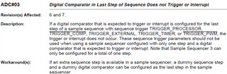
ADCSequenceStepConfigure(ADC0_BASE, ADC_SEQUENCE_NUMBER, 0,
ADC_CTL_CH7 | ADC_CTL_END | ADC_CTL_IE | ADC_CTL_CMP7);
ADCSequenceEnable(ADC0_BASE, ADC_SEQUENCE_NUMBER);
// Reset the ADC comparator
ADCComparatorReset(ADC0_BASE, ADC_CTL_CH7, true, true);
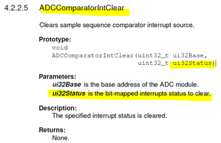
ADCComparatorIntClear(ADC0_BASE, ADC_SEQUENCE_NUMBER);
// Configure the ADC comparator
ADCComparatorConfigure(ADC0_BASE, ADC_CTL_CMP7,
ADC_COMP_INT_HIGH_ALWAYS);
ADCComparatorRegionSet(ADC0_BASE, ADC_CTL_CH7, 1024, 3600); // High threshold = 3600mV
ADCComparatorIntEnable(ADC0_BASE, ADC_SEQUENCE_NUMBER);
// Register the interrupt handler
IntMasterEnable();
ADCIntRegister(ADC0_BASE, ADC_SEQUENCE_NUMBER, adc_comparator_int_handler);
ADCIntEnable(ADC0_BASE, ADC_SEQUENCE_NUMBER);
IntEnable(INT_ADC0SS3);
}
// Once interrupt trigger, get the ADC value and print.
void adc_comparator_int_handler(void) {
ADCComparatorIntClear(ADC0_BASE, ADC_SEQUENCE_NUMBER);
uint32_t pui32ADC0Value[8] = {0};
ADCSequenceDataGet(ADC0_BASE, ADC_SEQUENCE_NUMBER, pui32ADC0Value);
printf("ADC value: %d", pui32ADC0Value[0]);
}
// Enable hw timer to trigger the ADC in every 1ms
void hw_timer_init()
{
SysCtlPeripheralEnable(SYSCTL_PERIPH_WTIMER1);
TimerDisable(WTIMER1_BASE, TIMER_A);
TimerConfigure(WTIMER1_BASE, TIMER_CFG_A_PERIODIC);
TimerLoadSet(WTIMER1_BASE, TIMER_A, SysCtlClockGet() / 1000 * 1);
TimerControlTrigger(WTIMER1_BASE, TIMER_A, true);
TimerEnable(WTIMER1_BASE,TIMER_A);
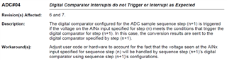
}Problem statement: ADC digital Comparator interrupt status is not set (ADCComparatorIntStatus(ADC0_BASE)).
Q1. How to get/calculate ADC Digital Comparator value(read value from which register)? (I would like to make sure that the ADC value is higher than 3600 mV)
Q2. Is the ADC Digital Comparator configuration correct?
Q3. How to make sure that the interrupt trigger due to the ADC value is higher than threshold?
Q3. How to make sure that the interrupt trigger due to the ADC value is higher than threshold?
Please help to clarify the problems. Thanks for your time and help.
Regards,
Suraj Pramanik