Part Number: MSPM0L1306-Q1
Other Parts Discussed in Thread: TLC6C5748-Q1, MSPM0L1306, SYSCONFIG
Hello,
Context:
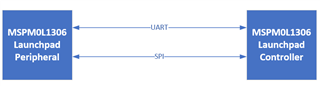
I am working on a reference design that involves pushing data from a launchpad to a reference design board using UART. The MSPM0L on the board will then send this data to the TLC6C5748-Q1 via SPI. I am creating code for the MSPM0L1306 on the board.
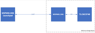
Code for the SPI transactions between the MSPM0L1306 and TLC6C5748 is implemented in the project (it is based on the spi_controller_multibyte_fifo_dma_interrupts example), but code for UART event handling is missing.
Since I am new to both UART and SPI, I opted to create a simple test setup using two launchpads to create code that handles both UART and SPI communication. I am using the spi_controller_multibyte_fifo_dma_interrupts & spi_peripheral_multibyte_fifo_dma_interrupts example, and adding some code from the uart_rw_multibyte_fifo_poll example. I can confirm that all the examples work for me. Overall, here are the conditions I expect for a successful test:
1) Peripheral sends a message via UART to controller.
2) Controller receives message. Controller replaces contents of gTxPacket with the uART message.
3) Controller & Peripheral fill up their TXFIFO.
4) Controller begins SPI transaction, and the same steps as the multibyte_fifo example occur.
Problem:
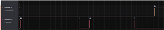
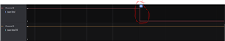
I am having trouble adding code to support the UART interface. When I run my code to test step 1, the Peripheral TX line stays low. It won't go high again even after resetting both launchpads. The only way to reset it is to power-cycle the boards.
When I disconnect TX and RX between the launchpads, I see the correct UART Message.

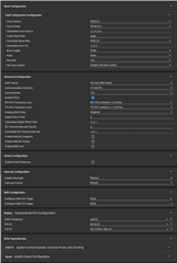
Can you provide guidance on how to go about fixing this? I suspect that it is either something with spi_controller_multibyte_fifo_dma_interrupts or sysconfig setup. Here is my code:
spi_controller_multibyte_fifo_dma_interrupts
/*
 * Copyright (c) 2020, Texas Instruments Incorporated
 * All rights reserved.
 *
 * Redistribution and use in source and binary forms, with or without
 * modification, are permitted provided that the following conditions
 * are met:
 *
 * *  Redistributions of source code must retain the above copyright
 *    notice, this list of conditions and the following disclaimer.
 *
 * *  Redistributions in binary form must reproduce the above copyright
 *    notice, this list of conditions and the following disclaimer in the
 *    documentation and/or other materials provided with the distribution.
 *
 * *  Neither the name of Texas Instruments Incorporated nor the names of
 *    its contributors may be used to endorse or promote products derived
 *    from this software without specific prior written permission.
 *
 * THIS SOFTWARE IS PROVIDED BY THE COPYRIGHT HOLDERS AND CONTRIBUTORS "AS IS"
 * AND ANY EXPRESS OR IMPLIED WARRANTIES, INCLUDING, BUT NOT LIMITED TO,
 * THE IMPLIED WARRANTIES OF MERCHANTABILITY AND FITNESS FOR A PARTICULAR
 * PURPOSE ARE DISCLAIMED. IN NO EVENT SHALL THE COPYRIGHT OWNER OR
 * CONTRIBUTORS BE LIABLE FOR ANY DIRECT, INDIRECT, INCIDENTAL, SPECIAL,
 * EXEMPLARY, OR CONSEQUENTIAL DAMAGES (INCLUDING, BUT NOT LIMITED TO,
 * PROCUREMENT OF SUBSTITUTE GOODS OR SERVICES; LOSS OF USE, DATA, OR PROFITS;
 * OR BUSINESS INTERRUPTION) HOWEVER CAUSED AND ON ANY THEORY OF LIABILITY,
 * WHETHER IN CONTRACT, STRICT LIABILITY, OR TORT (INCLUDING NEGLIGENCE OR
 * OTHERWISE) ARISING IN ANY WAY OUT OF THE USE OF THIS SOFTWARE,
 * EVEN IF ADVISED OF THE POSSIBILITY OF SUCH DAMAGE.
 */

#include "ti_msp_dl_config.h"

/*
 * Number of bytes for SPI packet size
 * The packet will be transmitted by the SPI controller.
 * This example uses FIFOs, and the maximum FIFO size is 4.
 */
#define SPI_PACKET_SIZE (4)

/* Data for SPI to transmit */
uint8_t gTxPacket[SPI_PACKET_SIZE] = {'M', 'S', 'P', '!'};

/* Data for SPI to receive */
uint8_t gRxPacket[SPI_PACKET_SIZE];

volatile bool gSPIDataTransmitted, gDMATXDataTransferred,
    gDMARXDataTransferred;

#define UART_PACKET_SIZE (4)

/* Delay for 5ms to ensure UART TX is idle before starting transmission */
#define UART_TX_DELAY (160000)

/* Data for UART to transmit */
uint8_t uARTtxPacket[UART_PACKET_SIZE] = {'A', 'D', '!', '!'};

/* Data received from UART */
uint8_t uARTrxPacket[UART_PACKET_SIZE];

volatile bool gCheckUART;

int main(void)
{
    SYSCFG_DL_init();
    NVIC_ClearPendingIRQ(UART_0_INST_INT_IRQN);
    NVIC_EnableIRQ(UART_0_INST_INT_IRQN);
    delay_cycles(UART_TX_DELAY);

    #if (ENABLE_LOOPBACK_MODE == true)
        /* Enable the internal loopback mode */
        DL_UART_enableLoopbackMode(UART_0_INST);
    #endif

    for (uint8_t i = 0; i < UART_PACKET_SIZE; i++) {
           uARTrxPacket[i] = DL_UART_receiveDataBlocking(UART_0_INST);
        }

    //while(gUARTEvent == false)
      //  __WFE();

    gSPIDataTransmitted   = false;
    gDMATXDataTransferred = false;
    gDMARXDataTransferred = false;

    /*
     * Configure DMA source, destination and size to transfer data from
     * gTxPacket to TXDATA. The DMA transfer will start when TX interrupt is
     * set, which it should already be set (which indicates that the SPI is
     * ready to transfer) so the DMA will begin this transfer when the channel
     * is enabled.
     */
    DL_DMA_setSrcAddr(DMA, DMA_CH0_CHAN_ID, (uint32_t) &gTxPacket[0]);
    DL_DMA_setDestAddr(DMA, DMA_CH0_CHAN_ID, (uint32_t)(&SPI_0_INST->TXDATA));
    DL_DMA_setTransferSize(
        DMA, DMA_CH0_CHAN_ID, sizeof(gTxPacket) / sizeof(gTxPacket[0]));

    /*
     * Configure DMA source, destination and size from RXDATA to gRxPacket.
     * The DMA transfer will start when the RX interrupt is set, which happens
     * when the device receives data.
     */
    DL_DMA_setSrcAddr(DMA, DMA_CH1_CHAN_ID, (uint32_t)(&SPI_0_INST->RXDATA));
    DL_DMA_setDestAddr(DMA, DMA_CH1_CHAN_ID, (uint32_t) &gRxPacket[0]);
    DL_DMA_setTransferSize(DMA, DMA_CH1_CHAN_ID, SPI_PACKET_SIZE);
    DL_DMA_enableChannel(DMA, DMA_CH1_CHAN_ID);

    DL_SYSCTL_disableSleepOnExit();
    NVIC_EnableIRQ(SPI_0_INST_INT_IRQN);

    /*
     * The SPI TX interrupt is already set, indicating the SPI is ready to
     * transmit data, so enabling the DMA will start the transfer
     */
    DL_DMA_enableChannel(DMA, DMA_CH0_CHAN_ID);

    /*
     * Wait in SLEEP mode until SPI_PACKET_SIZE bytes have been transferred
     * from gTxPacket to the SPI TXFIFO, and the DMA interrupt is triggered
     */
    while (false == gDMATXDataTransferred) {
        __WFE();
    }

    /*
     * Wait until the SPI has transmitted all the data and the TXFIFO
     * is empty
     */
    while (false == gSPIDataTransmitted) {
        __WFE();
    }

    /*
     * Wait in SLEEP mode until SPI_PACKET_SIZE bytes have been transferred
     * from SPI TXFIFO to gRxPacket, and the DMA interrupt is triggered
     */
    while (false == gDMARXDataTransferred) {
        __WFE();
    }

    /*
     * Set a SW breakpoint to check results.
     * If this example is used with the
     * spi_peripheral_multibyte_fifo_dma_interrupts example,
     * the expected data that will be received in gRxPacket is
     * {0x1, 0x2, 0x3, 0x4}.
     */
    __BKPT(0);

    while (1) {
        __WFI();
    }
}

void SPI_0_INST_IRQHandler(void)
{
    switch (DL_SPI_getPendingInterrupt(SPI_0_INST)) {
        case DL_SPI_IIDX_DMA_DONE_TX:
            /* DMA is done transferring data from gTxPacket to TXFIFO */
            gDMATXDataTransferred = true;
            break;
        case DL_SPI_IIDX_TX_EMPTY:
            /* SPI is done transmitting data and TXFIFO is empty */
            gSPIDataTransmitted = true;
            break;
        case DL_SPI_IIDX_DMA_DONE_RX:
            /* DMA is done transferring data from RXFIFO to gRxPacket*/
            gDMARXDataTransferred = true;
        default:
            break;
    }
}

void UART_0_INST_IRQHandler(void)
{
    switch (DL_UART_Main_getPendingInterrupt(UART_0_INST)) {
        case DL_UART_MAIN_IIDX_RX:
        {
            gCheckUART = true;
            // data = DL_UART_Main_receiveData(UART_0_INST);
            // DL_UART_Main_transmitData(UART_0_INST, data);
            break;
        }
        default:
            break;
    }
}
spi_peripheral_multibyte_fifo_dma_interrupts
/*
 * Copyright (c) 2020, Texas Instruments Incorporated
 * All rights reserved.
 *
 * Redistribution and use in source and binary forms, with or without
 * modification, are permitted provided that the following conditions
 * are met:
 *
 * *  Redistributions of source code must retain the above copyright
 *    notice, this list of conditions and the following disclaimer.
 *
 * *  Redistributions in binary form must reproduce the above copyright
 *    notice, this list of conditions and the following disclaimer in the
 *    documentation and/or other materials provided with the distribution.
 *
 * *  Neither the name of Texas Instruments Incorporated nor the names of
 *    its contributors may be used to endorse or promote products derived
 *    from this software without specific prior written permission.
 *
 * THIS SOFTWARE IS PROVIDED BY THE COPYRIGHT HOLDERS AND CONTRIBUTORS "AS IS"
 * AND ANY EXPRESS OR IMPLIED WARRANTIES, INCLUDING, BUT NOT LIMITED TO,
 * THE IMPLIED WARRANTIES OF MERCHANTABILITY AND FITNESS FOR A PARTICULAR
 * PURPOSE ARE DISCLAIMED. IN NO EVENT SHALL THE COPYRIGHT OWNER OR
 * CONTRIBUTORS BE LIABLE FOR ANY DIRECT, INDIRECT, INCIDENTAL, SPECIAL,
 * EXEMPLARY, OR CONSEQUENTIAL DAMAGES (INCLUDING, BUT NOT LIMITED TO,
 * PROCUREMENT OF SUBSTITUTE GOODS OR SERVICES; LOSS OF USE, DATA, OR PROFITS;
 * OR BUSINESS INTERRUPTION) HOWEVER CAUSED AND ON ANY THEORY OF LIABILITY,
 * WHETHER IN CONTRACT, STRICT LIABILITY, OR TORT (INCLUDING NEGLIGENCE OR
 * OTHERWISE) ARISING IN ANY WAY OUT OF THE USE OF THIS SOFTWARE,
 * EVEN IF ADVISED OF THE POSSIBILITY OF SUCH DAMAGE.
 */

#include "ti_msp_dl_config.h"

/*
 * Number of bytes for SPI packet size
 * The packet will be transmitted by the SPI peripheral.
 * This example uses FIFOs, and the maximum FIFO size is 4.
 */
#define SPI_PACKET_SIZE (4)

/* Data for SPI to transmit */
uint8_t gTxPacket[SPI_PACKET_SIZE] = {0x1, 0x2, 0x3, 0x4};

/* Data for SPI to receive */
uint8_t gRxPacket[SPI_PACKET_SIZE];

volatile bool gSPIDataTransmitted, gDMARXDataTransferred,
    gDMATXDataTransferred;

#define UART_PACKET_SIZE (4)

/* Delay for 5ms to ensure UART TX is idle before starting transmission */
#define UART_TX_DELAY (160000)

/* Data for UART to transmit */
uint8_t uARTtxPacket[UART_PACKET_SIZE] = {'T', 'I', '!', '!'};

/* Data received from UART */
uint8_t uARTrxPacket[UART_PACKET_SIZE];

int main(void)
{
    SYSCFG_DL_init();
    NVIC_ClearPendingIRQ(UART_0_INST_INT_IRQN);
    NVIC_EnableIRQ(UART_0_INST_INT_IRQN);

    delay_cycles(UART_TX_DELAY);

    #if (ENABLE_LOOPBACK_MODE == true)
        /* Enable the internal loopback mode */
        DL_UART_enableLoopbackMode(UART_0_INST);
    #endif

    /* Fills TX FIFO with data and transmits the data */
    DL_UART_Main_fillTXFIFO(UART_0_INST, &uARTtxPacket[0], UART_PACKET_SIZE);

    /* Wait until all bytes have been transmitted and the TX FIFO is empty */
    while (DL_UART_Main_isBusy(UART_0_INST))
        ;

    /*
     * Wait to receive the UART data
     * This loop expects UART_PACKET_SIZE bytes
     */
        /*
    for (uint8_t i = 0; i < UART_PACKET_SIZE; i++) {
       uARTrxPacket[i] = DL_UART_receiveDataBlocking(UART_0_INST);
    }*/

    gSPIDataTransmitted   = false;
    gDMARXDataTransferred = false;
    gDMATXDataTransferred = false;

    /*
     * Configure DMA source, destination and size to transfer data from
     * gTxPacket to TXDATA. The DMA transfer will start when TX interrupt is
     * set, which it should already be set (which indicates that the SPI is
     * ready to transfer) so the DMA will begin this transfer when the channel
     * is enabled. However the SPI Peripheral will not actually start
     * transmitted data until the SPI Controller initiates a transaction.
     */


    DL_DMA_setSrcAddr(DMA, DMA_CH0_CHAN_ID, (uint32_t) &gTxPacket[0]);
    DL_DMA_setDestAddr(DMA, DMA_CH0_CHAN_ID, (uint32_t)(&SPI_0_INST->TXDATA));
    DL_DMA_setTransferSize(
        DMA, DMA_CH0_CHAN_ID, sizeof(gTxPacket) / sizeof(gTxPacket[0]));
    DL_DMA_enableChannel(DMA, DMA_CH0_CHAN_ID);

    /*
     * Configure DMA source, destination and size from RXDATA to gRxPacket.
     * The DMA transfer will start when the RX interrupt is set, which happens
     * when the device receives data.
     */
    DL_DMA_setSrcAddr(DMA, DMA_CH1_CHAN_ID, (uint32_t)(&SPI_0_INST->RXDATA));
    DL_DMA_setDestAddr(DMA, DMA_CH1_CHAN_ID, (uint32_t) &gRxPacket[0]);
    DL_DMA_setTransferSize(DMA, DMA_CH1_CHAN_ID, SPI_PACKET_SIZE);
    DL_DMA_enableChannel(DMA, DMA_CH1_CHAN_ID);

    DL_SYSCTL_disableSleepOnExit();
    NVIC_EnableIRQ(SPI_0_INST_INT_IRQN);

    /*
     * Wait in SLEEP mode until data is transferred and DMA interrupt
     * is triggered
     */
    while (false == gDMATXDataTransferred) {
        __WFE();
    }

    /*
     * Wait until the SPI has transmitted all the data and the TXFIFO
     * is empty
     */
    while (false == gSPIDataTransmitted) {
        __WFE();
    }

    /*
     * Wait in SLEEP mode until data is received and DMA interrupt
     * is triggered
     */
    while (false == gDMARXDataTransferred) {
        __WFE();
    }

    /*
     * Set a SW breakpoint to check results.
     * If this example is used with the
     * spi_controller_multibyte_fifo_dma_interrupts example,
     * the expected data to receive in gRxPacket is
     * {'M', 'S', 'P', '!'}.
     */
    __BKPT(0);

    while (1) {
        __WFI();
    }
}

void SPI_0_INST_IRQHandler(void)
{
    switch (DL_SPI_getPendingInterrupt(SPI_0_INST)) {
        case DL_SPI_IIDX_DMA_DONE_TX:
            /* DMA is done transferring data from gTxPacket to TXFIFO */
            gDMATXDataTransferred = true;
            break;
        case DL_SPI_IIDX_TX_EMPTY:
            /* SPI is done transmitting data and TXFIFO is empty */
            gSPIDataTransmitted = true;
            break;
        case DL_SPI_IIDX_DMA_DONE_RX:
            /* DMA is done transferring data from RXFIFO to gRxPacket*/
            gDMARXDataTransferred = true;
            break;

        default:
            break;
    }
}
Let me know if you need anymore information.
Thanks!