This thread has been locked.

If you have a related question, please click the "Ask a related question" button in the top right corner. The newly created question will be automatically linked to this question.

AM2634-Q1: [MCAL]examples to detect rising edge

Part Number: AM2634-Q1
Other Parts Discussed in Thread: AM2634

Dear Champs,

To detect rising edge in GPIO, what is preferred MCAL module for this? Is there any way to implement it other than ICU MCAL?

In AM2634, there are 10 eCAPs. So, Can 10 x ICU MCAL module be run on AM2634 concurrently? 

Is there any limitation to input GPIO in ICU MCAL? Can any GPIO be used?

Could you please provide example how GPIO rising edge can be detected using ICU MCAL including port config, icu config, mcu config(xbar setting)?

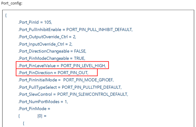
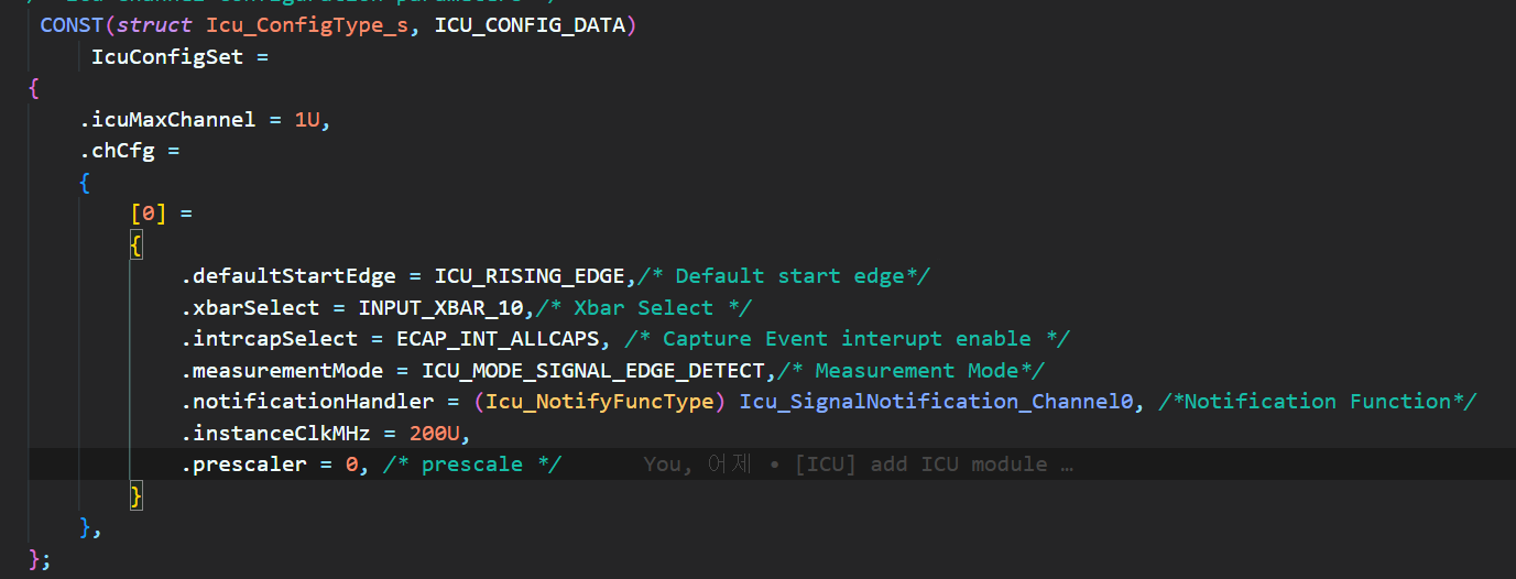
My customer tried it with below setting, but it didn't work.

Their MCAL version is v9.0.

Thanks and Best Regards,

SI.

  • Hi SI,

    To detect rising edge in GPIO, ICU is the only module.

    Yes, ICU can be use concurrently.

    No their is no limitation and we can use GPIO as input for ICU module.

    Below code snip will help customer how can we do this:

    Port_config:

        {
             .Port_PinId = 105,
             .Port_PullInhibitEnable = PORT_PIN_PULL_INHIBIT_DEFAULT,
             .Port_OutputOverride_Ctrl = 2,
             .Port_InputOverride_Ctrl = 2,
             .Port_DirectionChangeable = FALSE,
             .Port_PinModeChangeable = TRUE,
             .Port_PinLevelValue = PORT_PIN_LEVEL_HIGH,
             .Port_PinDirection = PORT_PIN_OUT,
             .Port_PinInitialMode =  PORT_PIN_MODE_GPIOEF,
             .Port_PullTypeSelect = PORT_PIN_PULLTYPE_DEFAULT,
             .Port_SlewControl = PORT_PIN_SLEWCONTROL_DEFAULT,
             .Port_NumPortModes = 1,
             .Port_PinMode =
             {            [0] =
                {
    
    
                    .mode = PORT_PIN_MODE_GPIOEF,
    
                    .muxmode = 7,
                },
             },
             .Port_PinDioRegId = (3 - 1U), /* GPIO register index is 0 based */
             .Port_PinDioChannelId = 6,
             .Port_RegOffsetAddr = PINK3_EPWM13_B,
             .Port_PinSignalName = (const sint8 *)"GPIOEF_70",
             .Port_PinName        = (const sint8 *)"PIN_K3",
             .Port_PinSetEdgeTrigger = FALSE,
             .Port_PinSelectEdgeTrigger = PORT_RISING_EDGE,
        },

    Like this you can generate for different GPIO pin.

    Icu_config: 

    /* Icu Channel Configuration parameters */
    CONST(struct Icu_ConfigType_s, ICU_CONFIG_DATA)
         IcuConfigSet =
    {
        .icuMaxChannel = 1U,
        .chCfg =
        {
            [0] =
            {
                .defaultStartEdge = ICU_RISING_EDGE,/* Default start edge*/
                .xbarSelect = INPUT_XBAR_0,/* Xbar Select */
                .intrcapSelect =  ECAP_INT_ALLCAPS, /* Capture Event interupt enable */
                .measurementMode = ICU_MODE_SIGNAL_EDGE_DETECT,/* Measurement Mode*/
                .notificationHandler = (Icu_NotifyFuncType) Icu_SignalNotification_Channel1, /*Notification Function*/
                .instanceClkMHz = 200U,
                .prescaler = 0, /* prescale */
            }
        },
    };

    Here we are using xbar_0 .But can be used anything.

    XBar_config:

    // for getting gpio output as input in ecap
    // In the second argument select the input_xbar you are selecting , so that with help of this you can configure whichever xbar you want to use for input to get into the icu
        SOC_xbarSelectInputXBarInputSource(CSL_CONTROLSS_INPUTXBAR_U_BASE, 0, 0, INPUT_XBAR_GPIO70, 0);
        SOC_xbarSelectInterruptXBarInputSource(CSL_CONTROLSS_INTXBAR_U_BASE, 22, 0, 0, 0, 0, 0, ( INT_XBAR_ECAP0_INT ), 0);

    Gpio_usage:

        if (mode == ICU_MODE_SIGNAL_EDGE_DETECT)
        {
            AppUtils_printf( APP_NAME ": Edge Detect Mode! \n\r");
    
            inputstate = Icu_GetInputState(ICU_CHANNEL);
            if(inputstate == ICU_ACTIVE)
               AppUtils_printf( APP_NAME ": input state is ICU_ACTIVE\n\r");
            else if (inputstate == ICU_IDLE)
               AppUtils_printf( APP_NAME ": input state is ICU_IDLE \n\r");
    
            Icu_EnableNotification(ICU_CHANNEL);
    
            Icu_EnableEdgeDetection(ICU_CHANNEL);
    
            uint32 counter=0;
            while(counter<10)
            { Dio_FlipChannel(70);
              volatile int v=0;
              while(v<1000)v++;
              counter++;
            }
    
            AppUtils_printf( APP_NAME ": SignalNotification for Single(Rising) Edge Detection Reached in 1 sec: %d \n\r", Icu_SignalNotificationNumber);
            Icu_SignalNotificationNumber = 0U;
    
            Icu_DisableEdgeDetection(ICU_CHANNEL);
        }

    Like this customer can use GPIO as input to ICU.

    Hope this information will help customer.

    Thanks 

  • Hi Mudit,

    Thanks for your immediate response. 

    To detect rising edge in GPIO, ICU is the only module.

    Yes, ICU can be use concurrently.

    Does this mean customer can check only 10 GPIOs rising edge as there are 10 eCAP in AM2634?

    I'll forward your detailed guide to customer. Thanks again for your kindness! 

    Thanks and Best Regards,

    SI.

  • Yes , 10 different GPIOs edge detection can be checked simultaneously with 10 ecap instances.

    Thanks

  • Hi Mudit Bhansali,

    Could you please provide more details on below Port_PinLevelValue and Port_PinDirection of 'Port_config' ?

    What does mean of 'PORT_PIN_OUT' in below?

    Thanks and Best Regards,

    SI.

  • Hi SI,

    Port Pin direction is used to signify that ok that GPIO should be used for output purpose or input purpose.

    Port Pin level value signifies the voltage level of a pin.

    Thanks

  • Hi Mudit Bhansali,

    Thanks for your response.

    Then, for their usecase - To detect rising edge in GPIO input, customer should set as below, right?

                .Port_PinLevelValue = PORT_PIN_LEVEL_HIGH,
                .Port_PinDirection = PORT_PIN_IN,

    And, when they want to detect rising edge in GPIO output, customer should set as below, right?

                .Port_PinLevelValue = PORT_PIN_LEVEL_HIGH,
                .Port_PinDirection = PORT_PIN_OUT,

    What confused here is that 'Port_PinDirection' is not 'Port_PinDirection' of ICU module. You meant is it is PinDrection of GPIO, right?

    Thanks and Best Regards,

    SI.

  • Hi SI,

    So here since calculation is done by ICU module and GPIO input is provided to ICU with help of X-Bar. So, customer should always set the Pin_Direction as Pin_out ,since they are transmitting the wave to ICU.

    Hope this clear your confusion.

    Thanks   

  • HI Mudit Bhansali,

    I'm sorry, but I'm still cofused.

    What I ask is the port setting of ICU and Pin_Direction of ICU module.

    Could you please clarify on the Port_Pin_Direction of ICU module? Should it be set as Pin_out?

    Thanks and Best Regards,

    SI.

  • No , For ICU module it will be Port_In But on the other hand for GPIO it will be Pin_out.

    Thanks

    Mudit

  • Mudit,

    Oh. Then the port config you mentioned in above is for GPIO port, not ICU. Is there any required port config for ICU in this usecase(detecting GPIO rising edge)?

    Thanks and Best Regards,

    SI.

  • Yup, The code snippit which i had shared is for GPIO port configuration.

    For ICU , the port config is default only, which we are providing in recommended configuration of port.

    Thanks

    Mudit

  • Mudit,

    I'm really appreciate for your clarification.

    Thanks and Best Regards,

    SI.