Part Number: RM57L843
Other Parts Discussed in Thread: DP83620, HALCOGEN
Greetings!
We are using the RM57L843 in a design that makes use of its Ethernet controller. The EMAC is connected via MII to a PHY (DP83620) which runs on its own 25 MHz crystal.
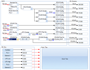
The RM57L843 datasheet (SPNS215C), section 6.6.3, states that this requires VCLKA4_DIVR_EMAC to be 25 MHz, so I set up PLL2 to 100 MHz and configure VCLKACON1 to select PLL2 as the source for VCLKA4, with a divider VCLKA4R = 3 for VCLKA4_DIVR. With this configuration, the EMAC runs perfectly fine, sending and receiving Ethernet packets in a stress test for days in a row.
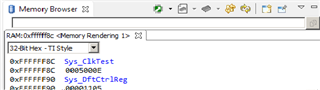
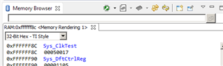
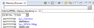
To verify the clocking, we have used the Clock Test feature to route VCLKA4 and VCLKA4_DIVR to the external outputs. We are measuring 100 MHz for VCLKA4 (SEL_GIO_PIN = 1110) as expected, but also 100 MHz for VCLKA4_DIVR (SEL_ECP_PIN = 01110) which looks wrong. However, the "EMAC clock output" setting for SEL_ECP_PIN), which does not seem to be explained any further in the documentation, gives the expected 25 MHz clock.
To investigate the discrepancy of the VCLKA4_DIVR measurement, I've changed the VCLKA4R divider to 7, which still gives 100 MHz for VCLKA4_DIVR but the expected 12.5 MHz for the "EMAC clock output". The EMAC still works perfectly fine with this setting. With other divider values, the "EMAC clock output" changes accordingly, so this clock test signal is obviously not related to the PHY clock. Still, VCLKA4_DIVR looks wrong.
Next, I changed the VCLKA4 clock source to the LF LPO and leave the divider at 7. Now I get 78 kHz for VCLKA4_DIVR on the clock test, and 9.7 kHz for the "EMAC clock output". Surprisingly, the EMAC still works fine.
So maybe VCLKA4(_DIVR) isn't actually needed for the EMAC (as suggested by a comment on Figure 6-6 of the datasheet)? To check this, I set VCLKA4_DIV_CDDIS in VCLKACON1. Now the "EMAC clock output" disappears, and the EMAC stops working. Similarly, when I disable the entire VCLKA4 clock domain via VCLKA4_OFF in the CDDIS register, I now measure 0 for both VCLKA4_DIVR and the "EMAC clock output" and the EMAC doesn't work.
So, apparently the EMAC requires some internal clock but has a very large tolerance regarding the frequency (10 kHz..100 MHz).
Questions:
- Why is it that, with the original settings, we measure 100 MHz for both VCLKA4 and VCLKA4_DIVR, instead of the expected 25 MHz for VCLKA4_DIVR?
- What does the "EMAC clock output" option of the Clock Test feature route to the external pin?
- What is the actual requirement for the frequency of VCLKA4/VCLKA4_DIVR to use an externally clocked PHY via MII?
Regards,
Christian