Part Number: TM4C1290NCZAD
Other Parts Discussed in Thread: MSP430FR5994
Hi,teams:
Now,I want to use TM4C1290NCZAD and MSP430FR5994 to transfer some data with SPI communication.
In my system, TM4C is the master and MSP430 is the slave.
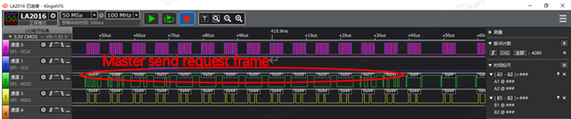
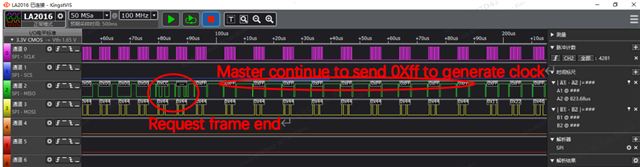
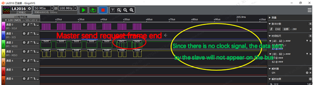
The host sends a request frame, and then the host continues to send some virtual signals to generate a clock signal,
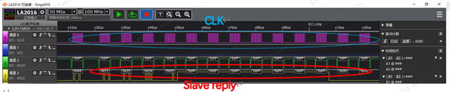
after the slave receives the command from the host, since the clock signal on the bus is normal at this time, the slave
Able to send data back to the host normally.
We all know that SPI is full-duplex communication.But in the process I described, SPI seems to be a half-duplex communication.
When the host sends data, the slave needs to rely on the clock signal generated by the host to send some virtual signals (such as 0XFF)
to send its own data back to the host.
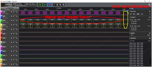
If during this process, due to some reasons, there is a problem with the clock signal, then the SPI will fail to send and receive data.
So i really want to know
(1)SPI full-duplex communication, how does the master and slave send and receive data at the same time,
why does the master not need to provide an additional clock signal to the slave?
(2)At present, the problem we have encountered is that occasionally the SPI communication between
the two chips cannot be communicated. Is it feasible for the master to send a virtual signal to generate a clock signal for the slave?
Please forgive my long-winded.I hope that some experts can patiently help me answer it after seeing it.