Other Parts Discussed in Thread: EK-TM4C1294XL, DRV2605L
HI TEAM
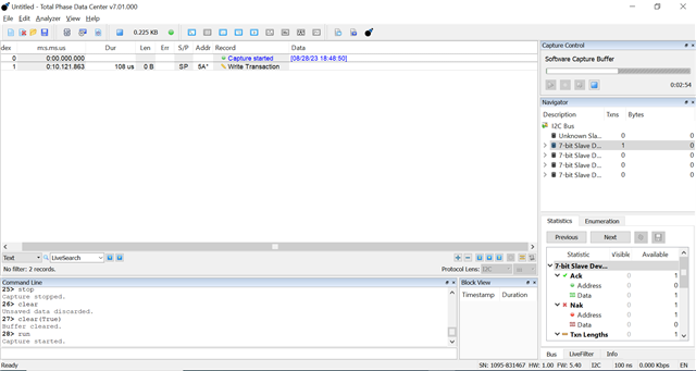
I am trying to up the I2C0 in the TM4C1294 EVK , but I2C master clock is not working , I have use the demo code (master_slave_loopback.c) provided by TI SDK , can you please help me to up the I2C clock
pull up is given from the I2C slave to the EVK I2C master, so there is no problem in pull up
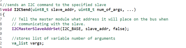
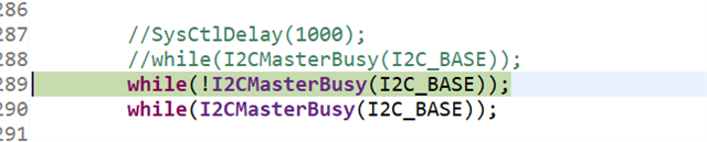
PFA of the code I used for testing , please suggest us what need to done from software or hardware side to fix the I2C clock issue.
Basically the code i have taken is form SDK provided by TI for TIVA series
please response
//*****************************************************************************
//
// master_slave_loopback.c - Example demonstrating a simple I2C message
// transmission and reception.
//
// Copyright (c) 2010-2020 Texas Instruments Incorporated. All rights reserved.
// Software License Agreement
//
// Redistribution and use in source and binary forms, with or without
// modification, are permitted provided that the following conditions
// are met:
//
// Redistributions of source code must retain the above copyright
// notice, this list of conditions and the following disclaimer.
//
// Redistributions in binary form must reproduce the above copyright
// notice, this list of conditions and the following disclaimer in the
// documentation and/or other materials provided with the
// distribution.
//
// Neither the name of Texas Instruments Incorporated nor the names of
// its contributors may be used to endorse or promote products derived
// from this software without specific prior written permission.
//
// THIS SOFTWARE IS PROVIDED BY THE COPYRIGHT HOLDERS AND CONTRIBUTORS
// "AS IS" AND ANY EXPRESS OR IMPLIED WARRANTIES, INCLUDING, BUT NOT
// LIMITED TO, THE IMPLIED WARRANTIES OF MERCHANTABILITY AND FITNESS FOR
// A PARTICULAR PURPOSE ARE DISCLAIMED. IN NO EVENT SHALL THE COPYRIGHT
// OWNER OR CONTRIBUTORS BE LIABLE FOR ANY DIRECT, INDIRECT, INCIDENTAL,
// SPECIAL, EXEMPLARY, OR CONSEQUENTIAL DAMAGES (INCLUDING, BUT NOT
// LIMITED TO, PROCUREMENT OF SUBSTITUTE GOODS OR SERVICES; LOSS OF USE,
// DATA, OR PROFITS; OR BUSINESS INTERRUPTION) HOWEVER CAUSED AND ON ANY
// THEORY OF LIABILITY, WHETHER IN CONTRACT, STRICT LIABILITY, OR TORT
// (INCLUDING NEGLIGENCE OR OTHERWISE) ARISING IN ANY WAY OUT OF THE USE
// OF THIS SOFTWARE, EVEN IF ADVISED OF THE POSSIBILITY OF SUCH DAMAGE.
//
// This is part of revision 2.2.0.295 of the Tiva Firmware Development Package.
//
//*****************************************************************************
#include <stdbool.h>
#include <stdint.h>
#include "inc/hw_i2c.h"
#include "inc/hw_memmap.h"
#include "inc/hw_types.h"
#include "driverlib/gpio.h"
#include "driverlib/i2c.h"
#include "driverlib/pin_map.h"
#include "driverlib/sysctl.h"
#include "driverlib/uart.h"
#include "utils/uartstdio.h"
//*****************************************************************************
//
//! \addtogroup i2c_examples_list
//! <h1>I2C Master Loopback (i2c_master_slave_loopback)</h1>
//!
//! This example shows how to configure the I2C0 module for loopback mode.
//! This includes setting up the master and slave module. Loopback mode
//! internally connects the master and slave data and clock lines together.
//! The address of the slave module is set in order to read data from the
//! master. Then the data is checked to make sure the received data matches
//! the data that was transmitted. This example uses a polling method for
//! sending and receiving data.
//!
//! This example uses the following peripherals and I/O signals. You must
//! review these and change as needed for your own board:
//! - I2C0 peripheral
//! - GPIO Port B peripheral (for I2C0 pins)
//! - I2C0SCL - PB2
//! - I2C0SDA - PB3
//!
//! The following UART signals are configured only for displaying console
//! messages for this example. These are not required for operation of I2C.
//! - UART0 peripheral
//! - GPIO Port A peripheral (for UART0 pins)
//! - UART0RX - PA0
//! - UART0TX - PA1
//!
//! This example uses the following interrupt handlers. To use this example
//! in your own application you must add these interrupt handlers to your
//! vector table.
//! - None.
//
//*****************************************************************************
//*****************************************************************************
//
// Number of I2C data packets to send.
//
//*****************************************************************************
#define NUM_I2C_DATA 3
//*****************************************************************************
//
// Set the address for slave module. This is a 7-bit address sent in the
// following format:
// [A6:A5:A4:A3:A2:A1:A0:RS]
//
// A zero in the "RS" position of the first byte means that the master
// transmits (sends) data to the selected slave, and a one in this position
// means that the master receives data from the slave.
//
//*****************************************************************************
#define SLAVE_ADDRESS 0x3C
//*****************************************************************************
//
// This function sets up UART0 to be used for a console to display information
// as the example is running.
//
//*****************************************************************************
void
InitConsole(void)
{
//
// Enable GPIO port A which is used for UART0 pins.
// TODO: change this to whichever GPIO port you are using.
//
SysCtlPeripheralEnable(SYSCTL_PERIPH_GPIOA);
//
// Configure the pin muxing for UART0 functions on port A0 and A1.
// This step is not necessary if your part does not support pin muxing.
// TODO: change this to select the port/pin you are using.
//
GPIOPinConfigure(GPIO_PA0_U0RX);
GPIOPinConfigure(GPIO_PA1_U0TX);
//
// Enable UART0 so that we can configure the clock.
//
SysCtlPeripheralEnable(SYSCTL_PERIPH_UART0);
//
// Use the internal 16MHz oscillator as the UART clock source.
//
UARTClockSourceSet(UART0_BASE, UART_CLOCK_PIOSC);
//
// Select the alternate (UART) function for these pins.
// TODO: change this to select the port/pin you are using.
//
GPIOPinTypeUART(GPIO_PORTA_BASE, GPIO_PIN_0 | GPIO_PIN_1);
//
// Initialize the UART for console I/O.
//
UARTStdioConfig(0, 115200, 16000000);
}
//*****************************************************************************
//
// Configure the I2C0 master and slave and connect them using loopback mode.
//
//*****************************************************************************
int
main(void)
{
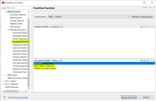
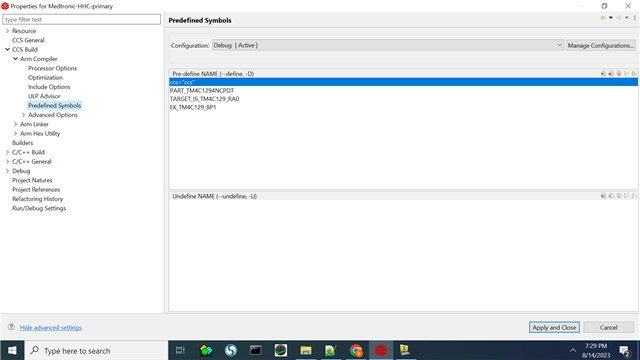
#if defined(TARGET_IS_TM4C129_RA0) || \
defined(TARGET_IS_TM4C129_RA1) || \
defined(TARGET_IS_TM4C129_RA2)
uint32_t ui32SysClock;
#endif
uint32_t pui32DataTx[NUM_I2C_DATA];
uint32_t pui32DataRx[NUM_I2C_DATA];
uint32_t ui32Index;
//
// Set the clocking to run directly from the external crystal/oscillator.
// TODO: The SYSCTL_XTAL_ value must be changed to match the value of the
// crystal on your board.
//
#if defined(TARGET_IS_TM4C129_RA0) || \
defined(TARGET_IS_TM4C129_RA1) || \
defined(TARGET_IS_TM4C129_RA2)
ui32SysClock = SysCtlClockFreqSet((SYSCTL_XTAL_25MHZ |
SYSCTL_OSC_MAIN |
SYSCTL_USE_OSC), 25000000);
#else
SysCtlClockSet(SYSCTL_SYSDIV_1 | SYSCTL_USE_OSC | SYSCTL_OSC_MAIN |
SYSCTL_XTAL_16MHZ);
#endif
//
// The I2C0 peripheral must be enabled before use.
//
SysCtlPeripheralEnable(SYSCTL_PERIPH_I2C0);
//
// For this example I2C0 is used with PortB[3:2]. The actual port and
// pins used may be different on your part, consult the data sheet for
// more information. GPIO port B needs to be enabled so these pins can
// be used.
// TODO: change this to whichever GPIO port you are using.
//
SysCtlPeripheralEnable(SYSCTL_PERIPH_GPIOB);
//
// Configure the pin muxing for I2C0 functions on port B2 and B3.
// This step is not necessary if your part does not support pin muxing.
// TODO: change this to select the port/pin you are using.
//
GPIOPinConfigure(GPIO_PB2_I2C0SCL);
GPIOPinConfigure(GPIO_PB3_I2C0SDA);
//
// Select the I2C function for these pins. This function will also
// configure the GPIO pins pins for I2C operation, setting them to
// open-drain operation with weak pull-ups. Consult the data sheet
// to see which functions are allocated per pin.
// TODO: change this to select the port/pin you are using.
//
GPIOPinTypeI2CSCL(GPIO_PORTB_BASE, GPIO_PIN_2);
GPIOPinTypeI2C(GPIO_PORTB_BASE, GPIO_PIN_3);
//
// Enable loopback mode. Loopback mode is a built in feature that is
// useful for debugging I2C operations. It internally connects the I2C
// master and slave terminals, which effectively let's you send data as
// a master and receive data as a slave.
// NOTE: For external I2C operation you will need to use external pullups
// that are stronger than the internal pullups. Refer to the datasheet for
// more information.
//
I2CLoopbackEnable(I2C0_BASE);
//
// Enable and initialize the I2C0 master module. Use the system clock for
// the I2C0 module. The last parameter sets the I2C data transfer rate.
// If false the data rate is set to 100kbps and if true the data rate will
// be set to 400kbps. For this example we will use a data rate of 100kbps.
//
#if defined(TARGET_IS_TM4C129_RA0) || \
defined(TARGET_IS_TM4C129_RA1) || \
defined(TARGET_IS_TM4C129_RA2)
I2CMasterInitExpClk(I2C0_BASE, ui32SysClock, false);
#else
I2CMasterInitExpClk(I2C0_BASE, SysCtlClockGet(), false);
#endif
//
// Enable the I2C0 slave module. This module is enabled only for testing
// purposes. It does not need to be enabled for proper operation of the
// I2Cx master module.
//
I2CSlaveEnable(I2C0_BASE);
//
// Set the slave address to SLAVE_ADDRESS. In loopback mode, it's an
// arbitrary 7-bit number (set in a macro above) that is sent to the
// I2CMasterSlaveAddrSet function.
//
I2CSlaveInit(I2C0_BASE, SLAVE_ADDRESS);
//
// Tell the master module what address it will place on the bus when
// communicating with the slave. Set the address to SLAVE_ADDRESS
// (as set in the slave module). The receive parameter is set to false
// which indicates the I2C Master is initiating a writes to the slave. If
// true, that would indicate that the I2C Master is initiating reads from
// the slave.
//
I2CMasterSlaveAddrSet(I2C0_BASE, SLAVE_ADDRESS, false);
//
// Set up the serial console to use for displaying messages. This is
// just for this example program and is not needed for I2C operation.
//
InitConsole();
//
// Display the example setup on the console.
//
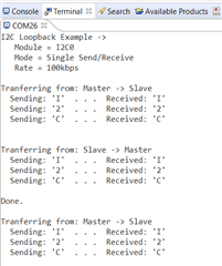
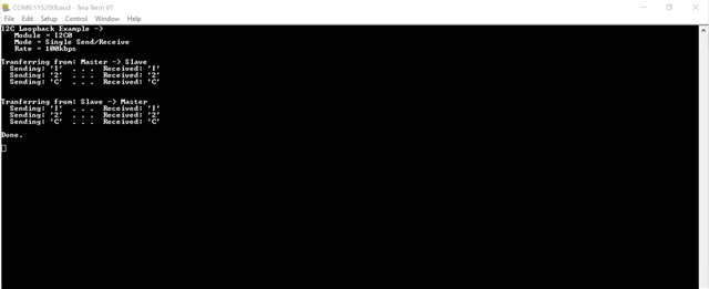
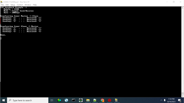
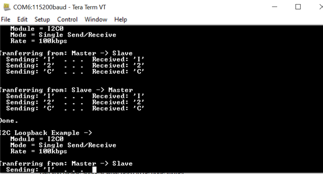
UARTprintf("I2C Loopback Example ->");
UARTprintf("\n Module = I2C0");
UARTprintf("\n Mode = Single Send/Receive");
UARTprintf("\n Rate = 100kbps\n\n");
//
// Initalize the data to send.
//
pui32DataTx[0] = 'I';
pui32DataTx[1] = '2';
pui32DataTx[2] = 'C';
//
// Initalize the receive buffer.
//
for(ui32Index = 0; ui32Index < NUM_I2C_DATA; ui32Index++)
{
pui32DataRx[ui32Index] = 0;
}
//
// Indicate the direction of the data.
//
UARTprintf("Tranferring from: Master -> Slave\n");
//
// Send 3 peices of I2C data from the master to the slave.
//
for(ui32Index = 0; ui32Index < NUM_I2C_DATA; ui32Index++)
{
//
// Display the data that the I2C0 master is transferring.
//
UARTprintf(" Sending: '%c' . . . ", pui32DataTx[ui32Index]);
//
// Place the data to be sent in the data register
//
I2CMasterDataPut(I2C0_BASE, pui32DataTx[ui32Index]);
//
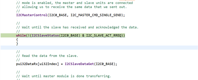
// Initiate send of data from the master. Since the loopback
// mode is enabled, the master and slave units are connected
// allowing us to receive the same data that we sent out.
//
I2CMasterControl(I2C0_BASE, I2C_MASTER_CMD_SINGLE_SEND);
//
// Wait until the slave has received and acknowledged the data.
//
while(!(I2CSlaveStatus(I2C0_BASE) & I2C_SLAVE_ACT_RREQ))
{
}
//
// Read the data from the slave.
//
pui32DataRx[ui32Index] = I2CSlaveDataGet(I2C0_BASE);
//
// Wait until master module is done transferring.
//
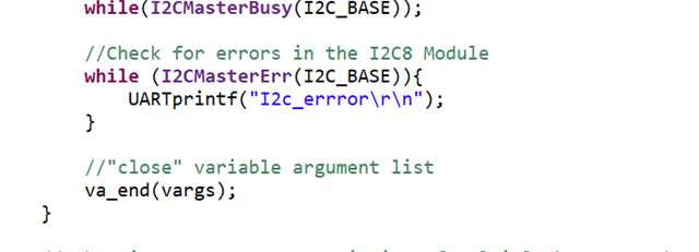
while(I2CMasterBusy(I2C0_BASE))
{
}
//
// Display the data that the slave has received.
//
UARTprintf("Received: '%c'\n", pui32DataRx[ui32Index]);
}
//
// Reset receive buffer.
//
for(ui32Index = 0; ui32Index < NUM_I2C_DATA; ui32Index++)
{
pui32DataRx[ui32Index] = 0;
}
//
// Indicate the direction of the data.
//
UARTprintf("\n\nTranferring from: Slave -> Master\n");
//
// Modifiy the data direction to true, so that seeing the address will
// indicate that the I2C Master is initiating a read from the slave.
//
I2CMasterSlaveAddrSet(I2C0_BASE, SLAVE_ADDRESS, true);
//
// Do a dummy receive to make sure you don't get junk on the first receive.
//
I2CMasterControl(I2C0_BASE, I2C_MASTER_CMD_SINGLE_RECEIVE);
//
// Dummy acknowledge and wait for the receive request from the master.
// This is done to clear any flags that should not be set.
//
while(!(I2CSlaveStatus(I2C0_BASE) & I2C_SLAVE_ACT_TREQ))
{
}
for(ui32Index = 0; ui32Index < NUM_I2C_DATA; ui32Index++)
{
//
// Display the data that I2C0 slave module is transferring.
//
UARTprintf(" Sending: '%c' . . . ", pui32DataTx[ui32Index]);
//
// Place the data to be sent in the data register
//
I2CSlaveDataPut(I2C0_BASE, pui32DataTx[ui32Index]);
//
// Tell the master to read data.
//
I2CMasterControl(I2C0_BASE, I2C_MASTER_CMD_SINGLE_RECEIVE);
//
// Wait until the slave is done sending data.
//
while(!(I2CSlaveStatus(I2C0_BASE) & I2C_SLAVE_ACT_TREQ))
{
}
//
// Read the data from the master.
//
pui32DataRx[ui32Index] = I2CMasterDataGet(I2C0_BASE);
//
// Display the data that the slave has received.
//
UARTprintf("Received: '%c'\n", pui32DataRx[ui32Index]);
}
//
// Tell the user that the test is done.
//
UARTprintf("\nDone.\n\n");
//
// Return no errors
//
return(0);
}
asap