This thread has been locked.

If you have a related question, please click the "Ask a related question" button in the top right corner. The newly created question will be automatically linked to this question.

TM4C129EKCPDT: Reserving untouched memory space

Part Number: TM4C129EKCPDT

Greetings,

I am trying to reserve a chunk of RAM to be used for information transfer from boot code and main application. I am writing the boot code now and trying to reserve the memory at 0x20000000 (len=0x400).

The following is my link command file:

--retain=g_pfnVectors
--retain=PrebootVector
--retain=Header
--retain=ExHeader

MEMORY
{
    FLASH (RX) : origin = 0x00000000, length = 0x00008000 LAST(__IMG_SIZE)
    SRAM (RWX) : origin = 0x20000400, length = 0x00040000 - 1K
}

/* The following command line options are set as part of the CCS project.    */
/* If you are building using the command line, or for some reason want to    */
/* define them here, you can uncomment and modify these lines as needed.     */
/* If you are using CCS for building, it is probably better to make any such */
/* modifications in your CCS project and leave this file alone.              */
/*                                                                           */
/* --heap_size=0                                                             */
/* --stack_size=256                                                          */
/* --library=rtsv7M4_T_le_eabi.lib                                           */

/* Section allocation in memory */

SECTIONS
{
    .pbootvec:    > 0x00000000
    .header:    > 0x00000120
    .intvecs:   > 0x00000200
    .text   :   > FLASH
    .const  :   > FLASH
    .cinit  :   > FLASH
    .pinit  :   > FLASH
    .init_array : > FLASH

    .vtable :   > 0x20000400
    .data   :   > SRAM
    .bss    :   > SRAM
    .sysmem :   > SRAM
    .stack  :   > SRAM
}

__STACK_TOP = __stack + 512;

Note that the SRAM range starts from 0x20000400.I am expecting that the this location (0x20000000 -0x200003ff) will not be touched. To verify this, I did a experiment to assign some value to this location. I start a debug session and make sure the values are assigned, and then I stop the debug session, without power reset the board, I start the debug session again. In theory, since the MCU has not been power reset, the assigned value should still be there. However, this is not the case. It seems that  this location is always initialized to certain value even if it is not in the defined SRAM range. Since nowhere else in the project is doing this, I suspect that it is the code in _c_int00() who did the trick.

I also did similar experiment on a different IDE (Semens' CodeBench) and the result was expected.

Is there a solution for this ?

  • Hi Tianle,

      Yes, it is part of the auto-init after _c_init00() is entered. However, I don't know how to provide a solution to only bypass a portion of the RAM from being initialized after a reset. I will need to move your post to our compiler expert for suggestion. Please note that E2E forum is under maintenance the next two days. Please expect delay response from our experts.  

  • The code generated by the compiler, and all the code in the RTS library, including the startup code, presumes the only valid memory ranges are the ones specified in the MEMORY directive.  Therefore this ...

    I suspect that it is the code in _c_int00() who did the trick

    ... is not correct.

    Since I cannot explain what happened, I have changed responsibility for this thread to the device software experts.

    Thanks and regards,

    -George

  • Hi, here are the simple steps for the issue:

    1. create a new CCS project with main() function

    2. modify 2 lines in the .cmd file as follows

        SRAM (RWX) : origin = 0x20000000, length = 0x00040000

        SRAM (RWX) : origin = 0x20000400, length = 0x00040000 - 1K

        .vtable :   > 0x20000000

        .vtable :   > 0x20000400

    3. define the main function

    int main(void)
    {
        uint32_t* test=0x20000000;
        *test = 0xaaaaaaaa;

        while(1);
    }

    4. debug the project, let the firmware run so that location 0x20000000 is assigned with value 0xaaaaaaaa

    5. stop the debug session and start it again without power resetting the target

    6. check the memory at 0x20000000

    The value at 0x20000000 is no longer 0xaaaaaaaa.

  • Hi Tianlei,

      What does it change at 0x20000000 in your case? I use your exact code. I try to do three things:

      1. A system reset

      2. A restart

      3. Stop debug session which will disconnect the debugger from the MCU. Once I disconnect, I immediate connect to the device again.

      But the value at 0x20000000 is not changed. The value 0xAAAAAAAA is not affected by the above three steps. 

    Below is the .cmd file I use which is pretty much the same as what you did - changing the SRAM starting address and .vtable. 

    --retain=g_pfnVectors
    
    /* The following command line options are set as part of the CCS project.    */
    /* If you are building using the command line, or for some reason want to    */
    /* define them here, you can uncomment and modify these lines as needed.     */
    /* If you are using CCS for building, it is probably better to make any such */
    /* modifications in your CCS project and leave this file alone.              */
    /*                                                                           */
    /* --heap_size=0                                                             */
    /* --stack_size=256                                                          */
    /* --library=rtsv7M3_T_le_eabi.lib                                           */
    
    /* The starting address of the application.  Normally the interrupt vectors  */
    /* must be located at the beginning of the application.                      */
    #define APP_BASE 0x00000000
    #define RAM_BASE 0x20000000
    
    /* System memory map */
    
    MEMORY
    {
        /* Application stored in and executes from internal flash */
        FLASH (RX) : origin = APP_BASE, length = 0x00100000
        /* Application uses internal RAM for data */
        SRAM (RWX) : origin = 0x20000400, length = 0x00040000 - 0x400
    }
    
    /* Section allocation in memory */
    
    SECTIONS
    {
        .intvecs:   > APP_BASE
    
        .text   :   > FLASH
        .const  :   > FLASH
        .cinit  :   > FLASH
        .pinit  :   > FLASH
        .init_array : > FLASH
    
        .vtable :   > 0x20000400
        .data   :   > SRAM
        .bss    :   > SRAM
        .sysmem :   > SRAM
        .stack  :   > SRAM
    
    
    }
    
    __STACK_TOP = __stack + 512;

  • Hi Charles,

    Did you terminate (the Red button) the previous debug session before starting the next one?

    From the image you posted, the memory content after 0x00000000 has the same pattern as mine, which looks like very much the vector table. If this area is untouched, shouldn't it be random values?

    Regards,

    Tianlei

  • Hi Tianlei,

      Yes, per my third experiment described earlier, I stopped the debug session by pressing the red square button. After I disconnect, I immediately connect to the target again. When viewing the memory content at 0x20000000, the value remains. Please note that when I connect back, the PC is still spinning at the while(1) from the previous debug session. 

  • Hi Charles,

    That meas the previous session was not terminated. If it was terminated, the new session should break at the entrance of main().

  • Hi Tianlei,

      In the first debug session, I run the code first. After the code is run, it wrote 0xAAAAAAAA to 0x20000000 and later reached the while(1). It is going to stay at while(1) even if you disconnect. Disconnect (when you press the red square button) only means the debugger is disengaged from the target device. The device will continue to run which is running the while(1). After I reconnect, I see the PC stay at while(1) and the memory does not change. Please try for yourself again or tell me how you 'terminate' the debug session. 

  • Hi Charles,

    I don't know why your device stays at while(1) when reconnected. Since the PC is already at while(1), it's not a surprise that 0xAAAAAAAA is still there.

    My observation is exactly the same as yours (when I press the red button, the debugger just dis-engages). The only difference is that when I reconnect (start a new debug session), the firmware will start over again and stop automatically at the first line of main().

    This is actually the issue I am reporting. At the first line of mian(), the value 0f 0xAAAAAAAA has not been assigned by the code, but if the device has run the code previously and not experienced a power-off, the value should still be retained since 'no code has intentionally changed the value since then'.

    Thanks

  • My observation is exactly the same as yours (when I press the red button, the debugger just dis-engages). The only difference is that when I reconnect (start a new debug session), the firmware will start over again and stop automatically at the first line of main().

    Hi Tianle,

      How did you reconnect? Did you reconnect by hitting the 'debug' button shown below? This will normally rebuild the project if there is any change to the code or the compile settings. It will then connect to the target, reload the code and the program will run and break at main(). 

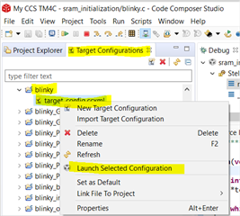
    The way i reconnect is to simply do a right-click on the target configuration file in the project directory and select Launch Selected Configuration. This will only connect to the target without restarting the code. 

     - First open Target Configurations under CCS->View->Target Configurations

     - Next go to your project and right-click on the target configuration file. I'm using the example blinky. In the blinky example project there is the target_config.ccxml file. Right-click on it and you will see another selection menu. 

     - Select Launch Selected Configuration. This will reconnect to your device. 

  • Hi Charles,

    I never used Launch Selected Configuration option in the Target Configuration tab.

    After I terminated the previous session, I would go to Run/Debug to restart a new session.

    They other way is to go to Run/Debug History and selected the most recent one, or go to Run/Debug Configurations... and then manually select the project to debug.

  • Hi Tianlei,

      Can you try what I showed? 

  • Hi Charles,

    I tried with you steps, but Launch Selected Configuration does not seem to work for me. After the option is selected, the IDE cannot successfully connect the target although it's already in debug session. In the Registers window all the registers are shown as 'Error: unable to read'. In the Memory window, all the locations are shown as '?'.

    I am not sure about the purpose of this. Even if I have the same result as yours, it won't prove anything. My intention is to let the code start over again, not just to be re-engaged by the debugger.

  • Hi Tianlei,

      I can reproduce what you have if I launch the debug session by clicking the debug button. When I do that, I will see the content at 0x20000000 overwritten with a pointer value to the top of the stack. In my example, my linker has the below snippet of code. I will see at 0x20000000 overwritten with a value of 0x20000600 which is the __STACK_TOP. The __STACK_TOP symbol is equal to __stack + 512. __stack is 0x20000400 and 512 is 0x200. Adding them produces 0x20000600. I don't know how CCS or the bootcode works in this regard and why it needs to put __STACK_TOP at 0x20000000. I will need to consult with our compiler expert. I'm attaching my very simple project here so our expert can reproduce it. Perhaps it is some CCS or linker settings to change but I don't know for sure. 

    MEMORY
    {
    /* Application stored in and executes from internal flash */
    FLASH (RX) : origin = APP_BASE, length = 0x00100000
    /* Application uses internal RAM for data */
    SRAM (RWX) : origin = 0x20000400, length = 0x00040000 - 0x400
    }

    /* Section allocation in memory */

    SECTIONS
    {
    .intvecs: > APP_BASE

    .text : > FLASH
    .const : > FLASH
    .cinit : > FLASH
    .pinit : > FLASH
    .init_array : > FLASH

    .vtable : > 0x20000400
    .data : > SRAM
    .bss : > SRAM
    .sysmem : > SRAM
    .stack : > SRAM


    }

    __STACK_TOP = __stack + 512;


    sram_init.zip

  •  Hi Tienlei,

      I think what has happened is that after you start a new debug session by pressing the debug button, the flash loader algorithm is copied to the RAM. It causes the processor to execute the flash loader algorithm. from RAM in order to load a new firmware image regardless if the image is updated or not. I will suggest you use my method if you really need to disconnect and reconnect by selecting the 'Launch Selected Configurations" for the target configuration file. 

  • Hi Charles,

    I did more experiments and it shows that it is not the loader algorithm who changed the value.

    Here is my project code:

    #include <stdint.h>
    #include "stdbool.h"
    #include "inc/hw_memmap.h"
    #include "driverlib/sysctl.h"
    #include "driverlib/gpio.h"

    int main(void)
    {

        uint32_t* test=0x20000000;
        int MemOk=(*test == 0xaaaaaaaa);
        *test = 0xaaaaaaaa;

        SysCtlPeripheralEnable(SYSCTL_PERIPH_GPIOF);
        GPIOPinTypeGPIOOutput(GPIO_PORTF_BASE, GPIO_PIN_0);
        GPIOPadConfigSet(GPIO_PORTF_BASE, GPIO_PIN_0, GPIO_STRENGTH_4MA, GPIO_PIN_TYPE_STD);


        GPIOPinWrite(GPIO_PORTF_BASE, GPIO_PIN_0, MemOk ? 0x00 : 0xff);


        while(1);
    }

    I am using a LED driven by a GPIO pin to indicate the value of the testing location. I burned the code into the MCU. On the first power-up, the LED is off, and then I reset the MCU by pulling the reset pin down while keeping the power. After the reset, the LED is still off. This means the location 0x20000000 is always changed by 'somebody'.

    Interestingly, If I change the testing location to 0x20003000, it works perfectly. On power-up, the LED is off, but on warm-reset, the LED is on.

  • Hi Tianlei,

     I'm not sure what you are trying to do with the below line. You have a == instead of =. Do you really mean to use ==  as a compare operator? 

    int MemOk=(*test == 0xaaaaaaaa);

  • Suppose you mean to use the == operator, I think you want to configure the reset pin behavior to generate a system reset rather than a simulated POR. 

    Add the below line to your code. 

    SysCtlResetBehaviorSet(SYSCTL_ONRST_EXT_SYS);

    When you do this, the first time after power cycle, the MemOk will be zero because *test has not been assigned a value yet and the (*test == 0xaaaaaaaa) will fail. With this, the LED will turn ON because MemOk ? 0x00 : 0xff will evaluate to write 1 to the PF0 to turn ON the LED. 

    If you press the reset pin the next time, *test still retains its prior value which is 0xaaaaaaaa. This makes (*test == 0xaaaaaaaa) true and MemOk becomes 1. When MemOk ? 0x00 : 0xff is evaluated, 0x00 is written to PF0 to turn OFF the LED. 

  • Hi Charles,

    MemOk will be assigned with 1 if the memory location (0x20000000) has value of 0xaaaaaaaa;

    otherwise it will be assigned with 0.

    This is the indication whether the value 0xaaaaaaaa is retained at location 0x20000000..

  • When the code begins to run (when main() is entered), it first checks the memory location 0x20000000 to see if it has value 0xaaaaaaaa. If yes, it will turn on the LED, otherwise it will turn off the LED.

    Then it will put value 0xaaaaaaaa to location 0x20000000 anyway.

    The expected behavior of code is:

    On power reset, the LED is supposed to be OFF.

    On warm reset, the LED is supposed to be ON.

  • Hi Tianlei,

      Have you added the below line yet? If you did, then there is no change to the RAM after you apply the reset pin. 

    SysCtlResetBehaviorSet(SYSCTL_ONRST_EXT_SYS);

  • Hi Charles,

    I am trying to understand your purpose. I am pulling down the reset (NMI) pin to force the MCU a warm reset. I don't need to configure it.

  • Hi Charles,

    I am trying to understand your purpose. I am pulling down the reset (NMI) pin to force the MCU a warm reset. I don't need to configure it.

    For power reset, I just unplug and plug back the power.

  • Hi Tianlei,

      There is a difference between system reset and a POR reset. Please refer to the reset behavior control in the datasheet for details. This is why I ask to change the reset behavior to only generate system reset, not internal POR reset. 

  • Hi Charles,

    After I added the line

    SysCtlResetBehaviorSet(SYSCTL_ONRST_EXT_SYS);

    to the code, it begins to work as expected.

  • Does it mean when debug session is entered, the CCS will force the MCU a power reset?

    Interestingly, I don't have such issue with the other IDE (CodeBench). Does it mean through the JTAG, the IDE can either force the MCU a system reset or a power on reset?  Just trying to explain my observation.

  • Hi Tianlei,

     As I explained earlier, a new debug session will force the CCS to copy the flash loader algorithm to RAM. This will overwrite the spaces needed by the flash loader. At first I thought this was your problem because you were doing experiments to disconnect the debug session and later launch a new debug session. 

      In your most recent experiment without the debugger connected, you reported that the RAM content was changed after you pull the reset pin. This prompts me to think it is related to how the reset pin is configured for its behavior. By default, a nRST pin will generate a simulated POR (more like a cold reset). It does a different device initialization than a system reset (warm reset). A cold reset will affect the content of RAM but not warm reset. 

      Perhaps for your CodeBench, a new debug session does not automatically load the flash loader algorithm to the RAM unless you ask it to. I don't know the tool enough to know in this regard. 

  • Thanks a lot Charles!