Other Parts Discussed in Thread: HALCOGEN
Hi all:
I am now working on chnaging the speed of EMIF bus which from 75MHz to 100MHz. Through the halcogen, I have successfully changed the frequency of EMIF into 100MHz and test the frequency through oscilloscope.
Then I want to use RTI module to act like “time stamp" to test copying data from SRAM to SDRAM. In this case I also reconfigure the rti module which maintain the 5Mhz. The test code is below:
#define rtos_realTimer         (*(volatile int*)0xFFFFFC10U)
/* USER CODE END */
int Wtbuf[1024]={0};
int  timedely,after;

int main(void)
{
/* USER CODE BEGIN (3) */
    rtiInit();
    sciInit();
    sciSendByte(sciREG4,0x34);
    int *prt=NULL;
    int before,i;
    prt =(int*)0x80000000;
    memset(Wtbuf,0,sizeof(Wtbuf));

    for(i=0;i<1024;i++)
    {
      Wtbuf[i]=i+0x5A5A0000;
    }

    before = rtos_realTimer;
    for(i=0;i<1024;i++)
    {
         prt[i] =Wtbuf[i];
    }
    after =rtos_realTimer;
    timedely =(after - before);

/* USER CODE END */

    return 0;
}
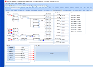
In my mapclocks, the HCLK is 100mhz, VCLK1=VCLK2=VCL3=100Mhz.
void mapClocks(void)
{
    uint32 SYS_CSVSTAT, SYS_CSDIS;

/* USER CODE BEGIN (11) */
/* USER CODE END */

    /** @b Initialize @b Clock @b Tree: */
    /** - Setup system clock divider for HCLK */

    systemREG2->HCLKCNTL = 2U;

    /** - Disable / Enable clock domain */
    systemREG1->CDDIS = (uint32)((uint32)0U << 4U ) /* AVCLK1 , 1 - OFF, 0 - ON */
                      | (uint32)((uint32)1U << 5U ) /* AVCLK2 , 1 - OFF, 0 - ON */
                      | (uint32)((uint32)0U << 8U ) /* VCLK3 , 1 - OFF, 0 - ON */
                      | (uint32)((uint32)0U << 9U ) /* VCLK4 , 1 - OFF, 0 - ON */
                      | (uint32)((uint32)0U << 10U) /* AVCLK3 , 1 - OFF, 0 - ON */
                      | (uint32)((uint32)0U << 11U); /* AVCLK4 , 1 - OFF, 0 - ON */


    /* Always check the CSDIS register to make sure the clock source is turned on and check
     * the CSVSTAT register to make sure the clock source is valid. Then write to GHVSRC to switch the clock.
     */
    /** - Wait for until clocks are locked */
    SYS_CSVSTAT = systemREG1->CSVSTAT;
    SYS_CSDIS = systemREG1->CSDIS;
    while ((SYS_CSVSTAT & ((SYS_CSDIS ^ 0xFFU) & 0xFFU)) != ((SYS_CSDIS ^ 0xFFU) & 0xFFU))
    {
        SYS_CSVSTAT = systemREG1->CSVSTAT;
        SYS_CSDIS = systemREG1->CSDIS;
    } /* Wait */

/* USER CODE BEGIN (12) */
/* USER CODE END */

    /** - Map device clock domains to desired sources and configure top-level dividers */
    /** - All clock domains are working off the default clock sources until now */
    /** - The below assignments can be easily modified using the HALCoGen GUI */

    /** - Setup GCLK, HCLK and VCLK clock source for normal operation, power down mode and after wakeup */
    systemREG1->GHVSRC = (uint32)((uint32)SYS_PLL1 << 24U)
                       | (uint32)((uint32)SYS_PLL1 << 16U)
                       | (uint32)((uint32)SYS_PLL1 << 0U);

    /** - Setup RTICLK1 and RTICLK2 clocks */
    systemREG1->RCLKSRC = (uint32)((uint32)1U << 24U)        /* RTI2 divider (Not applicable for lock-step device)  */
                        | (uint32)((uint32)SYS_VCLK << 16U) /* RTI2 clock source (Not applicable for lock-step device) */
                        | (uint32)((uint32)2U << 8U)         /* RTI1 divider */
                        | (uint32)((uint32)SYS_VCLK << 0U); /* RTI1 clock source */

    /** - Setup asynchronous peripheral clock sources for AVCLK1 and AVCLK2 */
    systemREG1->VCLKASRC = (uint32)((uint32)SYS_VCLK << 8U)
                         | (uint32)((uint32)SYS_VCLK << 0U);

    /** - Setup synchronous peripheral clock dividers for VCLK1, VCLK2, VCLK3 */
    systemREG1->CLKCNTL  = (systemREG1->CLKCNTL & 0xF0FFFFFFU)
                         | (uint32)((uint32)0U << 24U);
    systemREG1->CLKCNTL  = (systemREG1->CLKCNTL & 0xFFF0FFFFU)
                         | (uint32)((uint32)0U << 16U);

    systemREG2->CLK2CNTRL = (systemREG2->CLK2CNTRL & 0xFFFFFFF0U)
                         | (uint32)((uint32)0U << 0U);

    systemREG2->VCLKACON1 =  (uint32)((uint32)(2U - 1U) << 24U)
                           | (uint32)((uint32)0U << 20U)
                           | (uint32)((uint32)SYS_VCLK << 16U)
                           | (uint32)((uint32)(1U - 1U) << 8U)
                           | (uint32)((uint32)0U << 4U)
                           | (uint32)((uint32)SYS_VCLK << 0U);

/* USER CODE BEGIN (13) */
/* USER CODE END */

    /* Now the PLLs are locked and the PLL outputs can be sped up */
    /* The R-divider was programmed to be 0xF. Now this divider is changed to programmed value */
    systemREG1->PLLCTL1 = (systemREG1->PLLCTL1 & 0xE0FFFFFFU) | (uint32)((uint32)(1U - 1U) << 24U);
    /*SAFETYMCUSW 134 S MR:12.2 <APPROVED> " Clear and write to the volatile register " */
    systemREG2->PLLCTL3 = (systemREG2->PLLCTL3 & 0xE0FFFFFFU) | (uint32)((uint32)(1U - 1U) << 24U);

    /* Enable/Disable Frequency modulation */
    systemREG1->PLLCTL2 |= 0x00000000U;

/* USER CODE BEGIN (14) */
/* USER CODE END */

}
void rtiInit(void)
{
    /** - Setup NTU source, debug options and disable both counter blocks */
       rtiREG1->GCTRL = 0x80000000u;

       /** - Setup timebase for free running counter 0 */
       rtiREG1->TBCTRL = 0x00000000u;

       /** - Enable/Disable capture event sources for both counter blocks */
       rtiREG1->CAPCTRL = 0x00000000u;

       /** - Setup input source compare 0-3 */
       rtiREG1->COMPCTRL = 0x00000000u;

       /** - Reset up counter 0 */
       rtiREG1->CNT[0U].UCx = 0x00000000u;

       /** - Reset free running counter 0 */
       rtiREG1->CNT[0U].FRCx = 0x00000000u;

       /** - Setup up counter 0 compare value
       *     - 0x00000000: Divide by 2^32
       *     - 0x00000001-0xFFFFFFFF: Divide by (CPUC0 + 1)
       */
       rtiREG1->CNT[0U].CPUCx = 19U; // RTICLK = 100MHz; Counter0 clk = 5MHz  200ns


       /** - Reset up counter 1 */
       rtiREG1->CNT[1U].UCx = 0x00000000u;

       /** - Reset free running counter 1 */
       rtiREG1->CNT[1U].FRCx  = 0x00000000u;

       /** - Setup up counter 1 compare value
       *     - 0x00000000: Divide by 2^32
       *     - 0x00000001-0xFFFFFFFF: Divide by (CPUC1 + 1)
       */

       rtiREG1->CNT[1U].CPUCx = 19U;

       /** - Setup compare 0 value. This value is compared with selected free running counter. */
       rtiREG1->CMP[0U].COMPx = 5000U;

       /** - Setup update compare 0 value. This value is added to the compare 0 value on each compare match. */
       rtiREG1->CMP[0U].UDCPx = 5000U;

       /** - Setup compare 1 value. This value is compared with selected free running counter. */
       rtiREG1->CMP[1U].COMPx = 25000U;

       /** - Setup update compare 1 value. This value is added to the compare 1 value on each compare match. */
       rtiREG1->CMP[1U].UDCPx = 25000U;

       /** - Setup compare 2 value. This value is compared with selected free running counter. */
       rtiREG1->CMP[2U].COMPx = 40000U;

       /** - Setup update compare 2 value. This value is added to the compare 2 value on each compare match. */
       rtiREG1->CMP[2U].UDCPx = 40000U;

       /** - Setup compare 3 value. This value is compared with selected free running counter. */
       rtiREG1->CMP[3U].COMPx = 50000U;

       /** - Setup update compare 3 value. This value is added to the compare 3 value on each compare match. */
       rtiREG1->CMP[3U].UDCPx = 50000U;

       /** - Clear all pending interrupts */
       rtiREG1->INTFLAG = 0x0007000FU;

       /** - Disable all interrupts */
       rtiREG1->CLEARINTENA = 0x00070F0FU;

       /**   @note This function has to be called before the driver can be used.\n
       *           This function has to be executed in privileged mode.\n
       *           This function does not start the counters.
       */

       // notification
       rtiREG1->INTFLAG &= ~(int)1u; //PRQA S 3442 //access to volatile
       rtiREG1->SETINTENA   = 1u;

       // start
       rtiREG1->GCTRL |= 1u; // enable counter 0 //PRQA S 3442 //access to volat
}
The result is confused for me. In main function, the result of "timedely" equal to 2000 in 100Mhz however the result of "timedely" equal to 1500 in 75Mhz. which means the process of copying in 75M is faster than 100M.
Are there anything wrong in my configuration(clockmap,rti)?
Thanks&Regards
Li