This thread has been locked.

If you have a related question, please click the "Ask a related question" button in the top right corner. The newly created question will be automatically linked to this question.

RM57L843: IN LAUNCHXL2-RM57L BOARD WHILE CODE DUMPING FLASH MEMORY WAS NOT ERASING.

Part Number: RM57L843
Other Parts Discussed in Thread: UNIFLASH, LAUNCHXL2-RM57L, TPS2553

Hi TI Team,

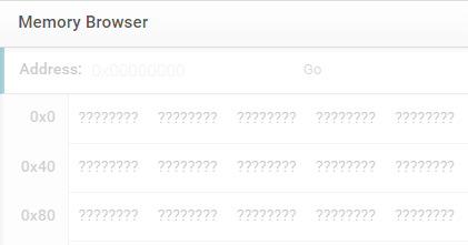
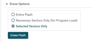
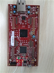
I am a LAUNCHXL2-RM57L board,it was working fine but suddenly while debigging (code compressor studio)flash memory was not erasing. Showing Load program error. I have erasing the flash using uniflash but not erasing.I have used on board usb debugger xds110.

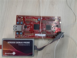
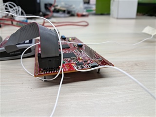
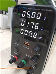
Now i am going to give external power to the board and programming using the jtag.I having xds200 debugger probe but i am not having the 20 pin connector between the board and the xds200 debugger.I want know what was the connector name,can we buy there separartly with out debugger and please provide some tips to do.

Please support us,

Thanks in Advance,

Best Regards,

A. Ajith Kumar

  • Hi Ajith,

    The components on the Launchpad are sensitive to ESD. It is recommended to use ESD protection (ESM mat and wrist strap) when handling the Launchpad.  

    Have you probe the power supplies (3.3V, 1.2V) on the board? Are you able to connect the XDS110 JTAG to the MCU?

  • Hi QJ Wang,

    When connecting to the on board usb debugger and power supply (xds110).The LAUNCHPAD was turned on. And I have got the 5V,3.3V and 1.2V on respective terminal. But when debugging erasing the flash memory was failed.

    Best Regards,

    A. Ajith Kumar

  • Hi Ajith,

    Please make sure the target has been connected. If MCU is connected, you can see the valid memory content in browser window:

    If the target is not connected, no data is displayed in browser window:

    Have you tried to ease the flash using CCS? 

  • Hi QJ Wang,

    The Target has been connected in uniflash software. I have mentioned attached below,

    I have tried to erase the flash in ccs.But not erasing.

  • Hi Ajith,

    Can you try to erase the flash sector by sector?

    I'd like to know which sector is not erasable? 

  • Hi QJ Wang,

    Yes, I have tried to erase by selecting selected sectors only. But not erasing. I have tried to erase bank0,bank1 and bank7 separately but not erasing.

  • Doesn't board power-cycling help? Does closing uniflash and re-opening uniflash help?

  • I have done the board power turned on and off and reset the board.it does not help me. The power cycling the board does not helps me. And I have closed the uniflash and reopened that. Does closing uniflash and re-opening uniflash does not helps me.

  • I noticed the error message in your previous post: unable access DAP (error 1170 @

    There are several potential root causes for the DAP error. Please see:

    https://software-dl.ti.com/ccs/esd/documents/ccs_debugging_jtag_connectivity_issues.html

    Please see the section called "Cannot access the DAP".

  • Hi QJ Wang,

    I have seen the Cannot access the DAP.I have attached the screen shot below, its not helped to solve the problem

  • Your configuration looks good.

    The "Cannot access the DAP" says that the issue may be caused by an invalid code that causes it to reset itself continuously. I don't know how your code works. Can you try to enable the CTI to stop the RTI counter at halt mode? The CTI can be enabled and disabled in the CCS scripts menu? 

    For RM57L8x, there is an on-chip CTI (Cross Trigger Interface) module that is programmable to route the debug acknowledge signal (DBGACK is asserted when halted) from the CPU to the rest of the devices. The CTI must be enabled first before the rest of the system such as RTI can see the DBGACK being asserted and in consequence stop the counter during debug state.

  • Hi QJ Wang,

    I have tried the CTI module enable and disabled in ccs script menu. But it not working.I have attached the screen share video for your reference.

  • Thank you for the video. When you are trying CTI scripts, the target is not connected to JTAG debugger. 

    Do you have any other Hercules EVM or launchpad to try? It looks like that the CPU can run the code to main(). I am not very clear why the flash cannot be erased. Is it possible for you to re-install the CCS which includes TMS570?RM57x flash configuration data?  

  • Hi QJ Wang,

    We have an another RM57 Launchpad(LAUNCHXL2-RM57L) the board was working with the same ccs.I have attached the both videos the working and notworking rm57 launchpad.

    Below Working LAUNCHXL2-RM57L VIDEO

    Below NOT Working LAUNCHXL2-RM57L VIDEO

  • Thank you. This means the flash driver and emulator driver work well. For the no-erasable board, you can connect the target to JTAG emulator, and run the existing LED-blinky code. Can you please compare the power consumption between working board and non-working board which run the same LED-blinky code? You can connect the 5V power supply to the header of LP board to read the current on the power supply..

    If you don't have separate power supply, can you check the board temperature and MCU surface temperature after running the code for a while. I'd like to know if there is any hardware damage on the non-working board.

  • Hi QJ Wang,

    Thanks for all the responses.

    There was no hardware damage in board. We have attached the photo of launchpad below,

    We have connected the JTAG emulator XDS200 and we give a power supply to the board externally, but it not connecting to the target.

    The current consumption of the working board 0.176A.

    The current consumption of not working board is 0.228A and after connecting the JTAG emulator 0.304A as shown below,

  • The no-working board consumes much more current (228-176=52mA). If the MCU on those two boards run the same code, the non-working board might have signal shorted. If the MCU doesn't execute any code, any difference between two boards? Does no-working board get hotter than another one?

  • Both the devices working and not working board runs on a code. The working board while no code was running consumes 0.169A ,while debugging consumes 0.254A and while executing the code consumes 0.292A.But the not working board consumes 0.228A initially and 0.304A after connect the debugger. The not working board not getting hotter than other one. No heating issues on the board.

    But after connecting the external degubber to the working board and external power supply in the jack. The board got erased the program and worked fine .after that when i connect on board usb debug xds110 .It was not connecting .I have connected the JP6 jumper. 

    The LED7 was not blow when usb debug probe was connected.What may be the couse happen to the working board.

    While connecting the xds200 debug probe I have n't remove the JP6 jumper. May be this reason issue was happen?

  • Is the external power supply removed from the board when you plug xds110 usb cable to the board? The board can be powered by either from usb cable or from J17.

    If only USB cable is plugged, what is the voltage level of at point 1 in below screenshot:

    The TPS2553 is a current-limit power-distribution switch, If point 1 is floating, the total resistance at ILIM is 220ohms which means it provides 130mA that is not big enough.

    Please double check the actual voltage level of 5V, 3.3V, and 1.2V if only USB cable is plugged.

  • When USB cable only was plugged, the voltage at point 1 was 0.401V . In R45 Resistor both ends getting 0.401V. But the resistor ohms value is fine 61.8K ohms.

    The voltage level of point 5V,3.3V and 1.2V was getting.

  • One more question:

    When you plug USB cable to the board, is the external debugger (xds200) connected to the JTAG header J18?

    When xds200 is connected to J18, the pin 8 is shorted to GND, so the tm4c129 (xds110) will disable xds110.

  • When you plug USB cable to the board, is the external debugger (xds200) connected to the JTAG header J18? NO

  • Hi Ajith,

    At point 1, the voltage level should be about 0V. If it is 0.401v, the point 1 is in floating, the total resistance between ILIM pin and GND is 220ohms, so TPS2553 will not provide enough current to the board and MCU. Erasing and programing flash consumes more current than regular MCU operations.

  • Hi QJ wang,

    Now the target device was connected but the program not erasing.CTI SETUP ALL CTI was done and DISABLE ALL CTI was done. next what to do.

  • Is the JTAG connection lost when you perform the flash erasing? 

    Please double check the voltage level at point #1 (not #2). The level should be around 0V, and voltage level at #2 is around 0.4V.

    As mentioned before, the TPS2533 doesn't most likely provide enough current for flash erase operation.