Other Parts Discussed in Thread: TMDS273EVM
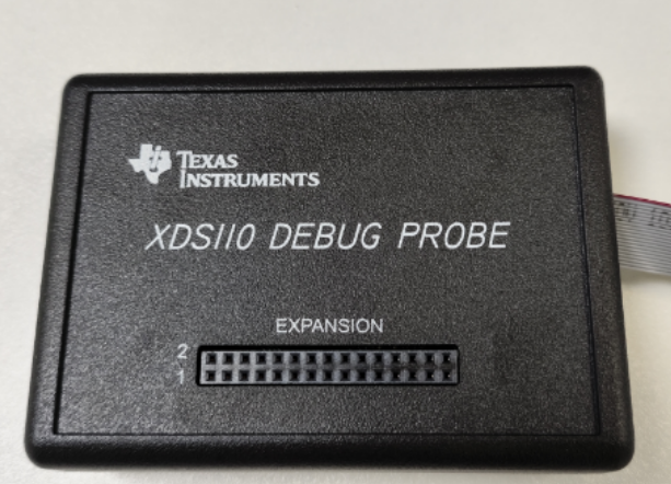
I made the dual-chip cascaded (AM273X + 2xAWR2243 EVM) hardware according to the design recommended by ti. The emulator uses this XDS110. How to use LVDS to collect data?

Regards,
Gary
This thread has been locked.
If you have a related question, please click the "Ask a related question" button in the top right corner. The newly created question will be automatically linked to this question.
I made the dual-chip cascaded (AM273X + 2xAWR2243 EVM) hardware according to the design recommended by ti. The emulator uses this XDS110. How to use LVDS to collect data?

Regards,
Gary
Hello Gary,
To clarify, are you asking about how to connect the XDS110 Debug Probe to your hardware and use the debugger or how to use the LVDS high-speed serial interface?
Are you using the TMDS273EVM or custom hardware?
Regards,
Erik
Hello Erik,
My goal is to achieve dual chip cascading (AM273X+2xAWR2243 EVM) hardware data acquisition, but as described in the document, LVDS data acquisition requires CCS DEBUG to load firmware. Then, I purchased XDS110 debugging probes and XDS110 test connect to print these:
[Start: Texas Instruments XDS110 USB Debug Probe_0]
Execute the command:
%Ccs_ Base%/common/uscif/dbgjtag - f% boarddatafile% - rv - o - S integrity
[Result]
-----[Print the board config pathname (s)]------------------------------------
C: Users LENOVO AppData Local TEXASI~1 CCS\
Ccs1240 0 0 BrdDate testBoard.dat
-----[Print the reset command software log file]-----------------------------
This utility has selected a 100/110/510 class product
This utility will load the adapter 'jioxds110. dll'
The library build date was' Jun 2 2023 '
The library built time was 12:47:07 '
The library package version is' 9.12.0.00150 '
The library component version is' 35.35.0.0 '
The controller does not use a programmable FPGA
An error occurred while hard opening the controller
-----[An error has occurred and this utility has aborted]--------------------
This error is generated by TI's USCIF driver or utilities
The value is' -267 '(0xfffffef5)
The title is' SC_ ERR_ XDS110_ TARGET_ SUPPLY '
The explanation is:
The controller could not detect valid target supply Check target
JTAG connection and/or connection setting specifying voltage level
[End: Texas Instruments XDS110 USB Debug Probe_0]
I don't know if there is a problem with the newly purchased XDS110 emulator
Regards,
Gary
Hello Gary,
Can you please explain the topology of the XDS110 JTAG connection? Are you able to provide the relevant schematic information for the XDS110 connection?
Regards,
Erik