This thread has been locked.

If you have a related question, please click the "Ask a related question" button in the top right corner. The newly created question will be automatically linked to this question.

MSPM0G3507: How to read channel values for the period time capture mode

Part Number: MSPM0G3507
Other Parts Discussed in Thread: SYSCONFIG,

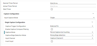
I'm able to perform a one shot measurement of a signal's period by configuring the capture mode to edge time capture, then starting the timer and reading the capture channel values in the first 2 ISR occurrences.  I wish to use the period time capture mode instead to avoid the risk that the first edge channel value will be overwritten by the 2nd edge before the ISR is serviced.  I don't understand what needs to be done to use this capture mode other than to call gCAPTURE_AUTOBAUD_CHARACTERCaptureConfig() with parameter DL_TIMER_CAPTURE_MODE_PERIOD_CAPTURE.

With this change I expected that the capture channel value should be the difference in clock ticks between the edges.  But I see that the timer LOAD value is the only value ever latched into the capture channel.  Can you tell me what I need to correct?

  • Hi Bryan,

    Have you looked at our timx_timer_mode_capture_duty_and_period example from the SDK?

    I also recommend looking in the TRM at section 23.2.3.1.2.2 Period Capture, there are proper Sysconfig configurations to assist in setting the timer to Period Capture. 

    I would need to see what your current implementation is to give advice on code changes.

    Regards,

    Luke

  • Hi Luke,

    My code is that of the timx_timer_mode_capture_edge_capture_LP_MSPM0G3507_nortos_ticlang example except that the capture mode has been changed from edge time to period capture counting.
    Section 23.2.3.1.2.2 is what made me aware that a period capture feature exists. The literature in this section seems a little unclear and is what prompted my question:
    "On each positive (or negative) edge of the CCP input, the TIMx.CTR value is both captured into the TIMx.CC register to generate a capture event."
    - Is this indicating that I should expect the counter value to latch to the same CC register AND set the interrupt flag every time the edge event occurs? How is this different from edge time capture mode?
    - The counter value doesn't latch for me in period capture mode. Instead, on an edge the counter's LOAD value is written into the CC register despite the fact that the counter is running before the edge occurs.  I see this when I break in the ISR.

    "After the capture event, set the TIMx.LOAD value back to 0 to reset the timer counter for the periodic CCP input signal."
    - I also see in the timx_timer_mode_capture_duty_and_period example that the counter value has to be reset on every edge event.
                        /* Manual reload is needed to workaround timer capture limitation */
                        DL_TimerG_setTimerCount(CAPTURE_0_INST, gLoadValue);
    - Why would this be necessary after the first edge? Our application will have very little time between the first and second edge events to service the ISR, so this would be an issue.
    - I'm attempting to switch from edge time to period capture time capture mode to avoid the risk that the first edge channel value will be overwritten by the 2nd edge before the ISR is serviced. Is this possible with the period capture mode or am I misunderstanding the way this mode operates? In other words will the period information be available in a CC register after the second edge event? If not, will the latched counter values for both edges still be available in CC registers after the second edge event?

  • Hi Bryan,

    Let me look further into this for you, I'll get back to you tomorrow.

    Regards,

    Luke

  • Hi Bryan,

    There is an errata [TIMER_ERR_0] on the Timer when doing Period capture. The capture duty and period example has the extra code to implement a workaround and still get the period and duty cycle. You can get the capture compare value on the "compare down event" interrupt, then manually load the load value to the timer.

    Due to the errata, you'll need to store 2 different edges to calculate the period, so it would take the same amount of time for processing as the edge timer.

    Regards,

    Luke

  • Hi Luke,

    I assume that were it not for the errata, period capture mode would require the interrupt to be serviced only once to find the period of a one shot pulse. 
    - Is this true?
    - Do you know if TI plans to fix this in the rev C silicon?
    - When will rev C silicon release?

  • Hi Bryan,

    Yes that was the intended operation of the period mode, the timer errata is getting addressed in future MSPM0 devices.

    Regards,

    Luke