This thread has been locked.

If you have a related question, please click the "Ask a related question" button in the top right corner. The newly created question will be automatically linked to this question.

AM2434: Recommended Typ PCB single-ended impedance and differential impedance for DDR and PCIE

Part Number: AM2434

Hi team,

This is FAE Jayden, My customer O-net use AM2434 and they have some questions about this socket.

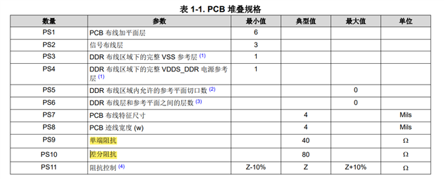
1.As for DDR4 design, there is APN about the AM2434 DDR4 PCB design: AM64x/AM243x DDR 电路板设计和布局指南 (Rev. A) (ti.com.cn); In APN, the recommended Typ PCB single-ended impedance and differential impedance is 40/80Ω.  If it is designed according to the conventional 50/100Ω, will it affect the signal quality? Or will 40/80Ω impedance meet most of the DDR4 chip on the market?

2. What is the recommended value for PCIE RX/TX PCB single-ended impedance and differential impedance of AM2434? The below picture shows On-net's design about PCIE, will it be ok?


3. Does AM2434 have any requirements for the material of the coupling capacitor?

Thanks

Brs

Jayden

  • Hi Jayden, 

    1. DDR4 trace impedances

    • Let me ask some other team members about this. My immediate suggestion would be to follow the recommendations in the layout guidelines application note since these are generated based on the results of our DDR controller characterization. 

    2.The PCIe standard dictates the interoperability of root and end-point devices, including the driver/receiver impedance match. 50-ohm single-ended / 100-ohm differential pairs are the standard and should be followed in all designs including the AM243x PCIe. 

    3. The PCIe standard dictates the AC-coupling / DC-blocking nominal capacitance of 100nF. In terms of materials, our characterization systems typically use X7R or better capacitors for these designs so that the differences between capacitors, and over temperature/time does not significantly impact performance. From From a PCB design perspective, the goal is to minimize the impedance discontinuity that the capacitors pads add to the transmission-lines. Using smaller 0201 capacitors can help with this. Also leaving return path voids underneath the capacitors. But you would need to make these PCB design decisions based on a 3D EM field solver or PCB measurements. 

  • Hi Jayden, 

    Our DDR4 controller and DDR3 memories support a wide range of driver/termination values: 34,40,48,60,80,120,240-ohm. 

    The table PS9 and PS10 are one supported example at the 40-ohm single-ended setting. If the routing is done well, there should be no issue with supporting 50-ohm lines. Most PCB fab will be +/-5% or +/-10% tolerance anyway. The 48-ohm setting would probably be best to start with. 

    Thank you,

    -Randy

  • Got it! Thanks, Randy.

    Brs

    Jayden