


Part Number: TMS570LC4357
Hello,
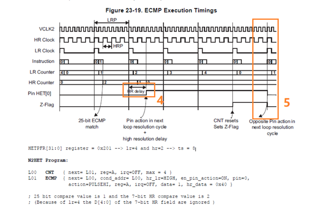
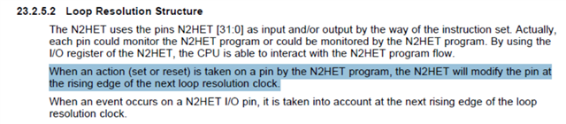
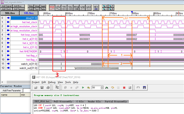
Question 1: About the effective point of pin behavior. At position 5 in Figure 1, the pin action is executed on the rising edge of LRP, which is consistent with the problem description in Figure 2, but the actual simulation results show that it is executed on the falling edge of LRP, as shown at position 3 in Figure 3. Which one should be used for actual operation?
Question 2: Regarding the effective point of the pin behavior during HR delay. At position 4 in Figure 1, HR delay starts to calculate the HR cycle with the rising edge of LRP and executes the pin behavior at the rising edge of HR. But in the simulation, it is found that if the calculation of the HR period is started from the rising edge of LRP in the manner shown in position 2 in Figure 3, the HR delay period is wrong. The simulation result seems to be that HR delay starts to calculate the HR period from the falling edge of LRP and is executed on the falling edge of HR. The pin behavior, as shown at position 1 in Figure 3, does not match the description in Figure 1. Which one should be used for actual operation?
Regards,
Gary

