This thread has been locked.

If you have a related question, please click the "Ask a related question" button in the top right corner. The newly created question will be automatically linked to this question.

TMS570LS3137: TMS570LS3137 Analog pin read as digital

Part Number: TMS570LS3137
Other Parts Discussed in Thread: HALCOGEN

Hello everyone,

We are developing an application with TMS570.
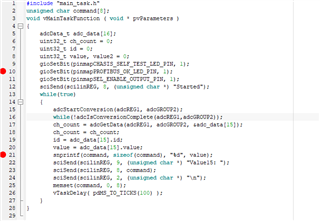
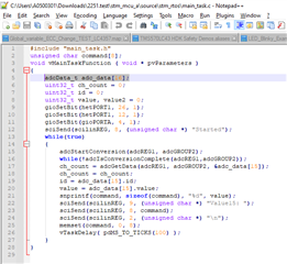
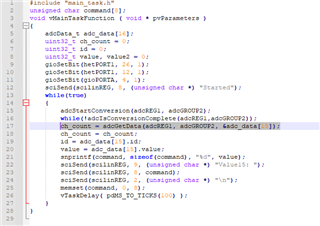
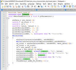
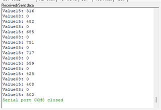
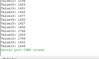
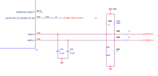
I want to read the AD1[15] pin digitally, that is, as logic HIGH or LOW. When I start the ADC, the incoming values are not always consistent.
It happens like this:
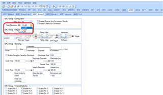
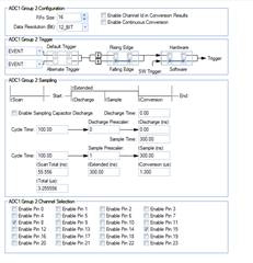
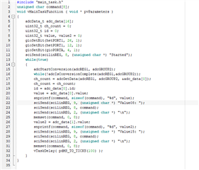
I select the AD1[15] pin as enable from GROUP1 with Halcogen.
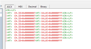
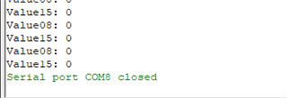
When I start the ADC, the value from adcData_t is 101.
However, for example, when the AD1[8] pin is connected to 3V3, it changes to 158. However, AD1[8] was not enabled via halcogen.
How can I read only the data on the relevant analogue pins digitally?

Thank you for your help

  • Hi Ali,

    First of all, something wrong with your measurement:

    However, for example, when the AD1[8] pin is connected to 3V3, it changes to 158.

    As you can see, the ADC can be operated in 8bit, 10bit or 12bit resolutions right, so that means if you operated ADC in 8 bit resolution with 3.3v ref then when you connected 3.3v to ADC pin then you should get 0xFF (255) value.

    or else if you operate ADC in 10 bit resolution with 3.3v ref then you should get 0x3FF (1023) value, if you connected 3.3v input.

    or else if you operate ADC in 12 bit resolution with 3.3v ref then you should get 0xFFF (4095) value, if you connected 3.3v input.

    For example, as you can see below pic when i operated ADC in 12 bit resolution with 3.3v ref and 3.3v input.

    Please make sure you are doing right setup.

    I want to read the AD1[15] pin digitally, that is, as logic HIGH or LOW.

    You can't directly operate Analog input into digitally but you can do one thing:

    Actually the digital input pins will operate like this:

    If input voltage is in between 0 to 0.8v then the controller will treat input as a logic LOW.

    Or else if the input is in between 2 to 3.3v then the controller will treat the input as logic HIGH.

    And if it falls in between(0.8v to 2v), it is unpredictable. So, if you want to operate analog input as digital input then after reading the analog input value then convert its equivalent voltage and compare the equivalent voltage with the above limits i mentioned and based on the range you can consider the input as logic HIGH or logic LOW.

    Example:

    If i am operating ADC in 12 bit resolution then if i get ADC value as 4000 (0xFA0) then its equivalent analog voltage will be 3.22v according to below formula

    Analog voltage = (3.3 / 4095) * Analog_Value

    as my input voltage is 3.22 which is above 2v right so i will consider it as logic HIGH in the code and do the necessary action.

    --

    Thanks & Regards,
    Jagadish.

  • Hi ,

    Thank you for your response. But,

    I understand the relationship between ADC resolution and ADC resolution. I expect a value accordingly, but changes in other pins affect ADC data.
    First of all, I want to make sure of this:
    We use the following commands to read from the ADC pin:
    adcEnableNotification(adcREG1, adcGROUP1);
    adcStartConversion(adcREG1, adcGROUP1);
    while( !adcIsConversionComplete(adcREG1, adcGROUP1) ;
    adcStopConversion(adcREG1, adcGROUP1);

    Variable created to read incoming data adcData_t data;
    value = (uint16_t) adcGetData(adcREG1, adcGROUP1, &data);
    If it is appropriate so far, I would like to ask the following. Specifically, how will I obtain the data on ADC pin 15.
    Because I see that the value here changes depending on other inputs.

  • Hi Ali,

    Here is a working example on LS3137 for your reference.

    Please compare the code with yours.

    ADC_TEST_LS3137.zip

    --

    Thanks & regards,
    Jagadish.

  • Hi ,

    I compared your code to mine. But I didn't get the result I wanted.

    The problem is that, I have configured ADC register with below in the Halcogen.

    Enabled Pin 8 and Enabled Pin 15.

    And I write following code for reading ADC Group 2 Channel[15].

    The analog reference pins are configured as follows:

    ADREFHI -> 3.3V

    ADREFLO -> GND

    The problem starts here:

    I get the different value for different input in analog inputs.

    If I connected AD1[8] and AD1[15] to 3.3V I get the value 993 or 992.

    If connected AD1[8] to GND and AD1[15] to 3.3v, I get the value 0.

    If I disabled AD1[8] channel in the Halcogen and I connected AD1[15] to 3.3V, I get the value ~2590 (same code).

    I don't understand this. I have to use several ADC pins for digital input. But the channels affect each other. How can I use the ADC reading separately.

    Thank you for your support.

  • Hi,

    Can you please zip your complete project and attach it for debugging purpose at my end?

    --

    Thanks & regards,
    Jagadish.

  • Hello,

    I have added code.

    I'm using the IAR Compiler. I hope this is not a problem for you.

  • Hi,

    Few things i am not clear with your code.

    The main thing is below:

    1. You declared "adc_data" array with 16 

    That means your array will start from the adc_data[0] and will end at adc_data[15] right?

    And you selected two channels right ADC_8 and ADC_15.

    If you pass the last address of the array i.e. adc_data[15] address to the function "adcGetData", where will be the second channel data will be stored?

    The first channel will be stored in adc_data[15] and then for second channel the array will get over flowed right?

    Why don't you pass the starting address to the function i.e. &adc_data[0]? If you do that the channel 8 data will  be stored at adc_data[0] and channel 15 data will be store at adc_data[1]

    2. What is the purpose of command array?

    Where data will be moved to this command?

    --

    Thanks & regards,
    Jagadish.

  • Hi,

    1) Yes adcData[16] was an attempt to keep adc data between 0 and 16.

    Yes, I activated two channels as channels via Halcogen.

    Yes, I did as you said. I was able to see zero data on two separate channels. Thank you.


    I skipped the step where the data will be transferred to the next element.

    The problem seems to be solved, but at the moment, channels 8 and 15 are affected by each other.
    So it is like this:
    When channel 8 and channel 15 are connected to zero, both values are zero.


    When Channel 8 is connected to GND channel 15 3.3v, I see a value between 800 and 300 for Channel 15.


    When channel 8 and channel 15 are connected to 3.3v, it returns a value between 1500-1800 for channel 15 and channel 8. 

    The problem here is that I cannot get the same value consistently.
    Is it due to voltage drop or some other reason?

    2) Command array is a just character string for print to serial port.

    Thank you for your labour

  • Hi Ali,

    When Channel 8 is connected to GND channel 15 3.3v, I see a value between 800 and 300 for Channel 15.
    When channel 8 and channel 15 are connected to 3.3v, it returns a value between 1500-1800 for channel 15 and channel 8. 

    These results are not expected.

    I mean as we are operating in 12-bit resolution, so if we connect 3.3v then the result should be close to the 4095.

    Can you please help me on these things?

    1. What is the board you are using? Is it TI specific or custom board?

    2. Why don't you try simple bare-metal code without RTOS first? Your ADC code looks fine for me but may be due to RTOS scheduler or with any other peripherals in RTOS it might affect right? so first just try ADC alone on simple bare-metal code without RTOS?

    If we test with bare-metal code, then we can easily understand whether it is a hardware issue or software?

    --

    Thanks & regards,
    Jagadish.

  • Hi again,

    1. What is the board you are using? Is it TI specific or custom board?

    I'm using the Texas Instruments Hercules board.

    Why don't you try simple bare-metal code without RTOS first? Your ADC code looks fine for me but may be due to RTOS scheduler or with any other peripherals in RTOS it might affect right? so first just try ADC alone on simple bare-metal code without RTOS?

    It's nice idea. I updated the code and try again. But the results are same. (

    #include "sys_main.h"
    void wait(uint32 time);
    int main(void)
    {
        _enable_interrupt_();      // For receiving data via UART(SCI) communication.
        sciInit();                          /* For serial communication, this function need to be initalized.                                      */
        adcInit();                          /* Analog reading initialization.                                                                      */
        gioInit();                          /* General purpose I/O pins.                                                                           */  
        adcData_t adc_data[16];
        uint32_t ch_count = 0;
        uint32_t id = 0;
        uint32_t value, value2, value3 = 0;
        unsigned char command[8];
        gioSetBit(hetPORT1, 26, 1);
        gioSetBit(hetPORT1, 12, 1);
        gioSetBit(gioPORTA, 4, 1);
        sciSend(scilinREG, 8, (unsigned char *) "Started");
        while(true)
        {   
            adcStartConversion(adcREG1, adcGROUP2);
            while(!adcIsConversionComplete(adcREG1,adcGROUP2));
            ch_count = adcGetData(adcREG1, adcGROUP2, &adc_data[0]);
            ch_count = ch_count;
            id = adc_data[0].id;
            value = adc_data[0].value;
            snprintf(command, sizeof(command), "%d", value);
            sciSend(scilinREG, 9, (unsigned char *) "Value00: ");
            sciSend(scilinREG, 8, command);
            sciSend(scilinREG, 2, (unsigned char *) "\n");
            memset(command, 0, 8);
            value2 = adc_data[1].value;
            snprintf(command, sizeof(command), "%d", value2);
            sciSend(scilinREG, 9, (unsigned char *) "Value08: ");
            sciSend(scilinREG, 8, command);
            sciSend(scilinREG, 2, (unsigned char *) "\n");
            memset(command, 0, 8);
            value3 = adc_data[2].value;
            snprintf(command, sizeof(command), "%d", value3);
            sciSend(scilinREG, 9, (unsigned char *) "Value15: ");
            sciSend(scilinREG, 8, command);
            sciSend(scilinREG, 2, (unsigned char *) "\n");
            memset(command, 0, 8);
            wait(0xFFFFFF);
        }
    
        return 0;
    }
    
    void wait(uint32 time)
    {
        while(time){time--;};
    }
    Bare metal code is attached)

    After that I changed my ADREFHI pin to external 3.3 Pin and I connected AD1_15 to this external 3.3V bus.

    The results are below:

    It's closer to 4095 than it used to be.

    I think the problem in the analog references and input voltage. Am I right?

    Thanks& Best regards

  • Hi Ali,

    I think the problem in the analog references and input voltage. Am I right?

    Yes, you are right, it is due to analog reference voltage.

    The reference voltage is depends on the R1x and R2x. If J8 is not mounted on your board then the reference voltage will be 5v. If J8 connected then the reference voltage will becomes 3V.

    If you connect external 3.3v to the ADREFHI, then you should remove the R22 and R31 for more accurate results.

    --

    Thanks & regards,
    Jagadish.

  • Ohh that nice information to me. J8 jumper is removed before and I didn't see.

    If you connect external 3.3v to the ADREFHI, then you should remove the R22 and R31 for more accurate results.

    I didn't know that before. Thank you

    It is done right now. I'm receiving 4095.

    Thank you

    Best Regards.

  • It is done right now. I'm receiving 4095.

    Good to hear that.