This thread has been locked.

If you have a related question, please click the "Ask a related question" button in the top right corner. The newly created question will be automatically linked to this question.

RM44 : ADC Value lesser than the actual Value

Part Number: RM44L920
Other Parts Discussed in Thread: HALCOGEN

Hi,

I am using RM44 ADC module to measure the Wheel speed sensor analog values , found that the actual analog value was supposed to be 1.6 volt (aprox) , but the adc value measured from the Micro controller is 1.1 volt.

1) Do i need to calibrate ADC at program initially to get the calibration value?
2) Do i need to use Sampling capacitor Discharge? if so what should be my sampling time?

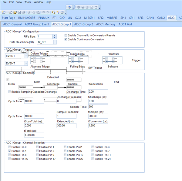
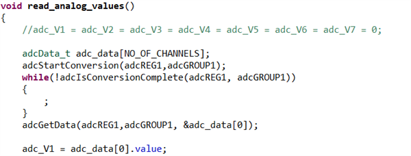
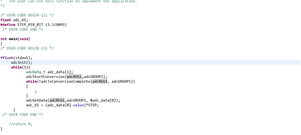
I am attaching my Code and Halcogen configurations:

  • Hi Karthik,

    Which board you are using?

    Is it a custom board or any TI specific board?

    And what is the ADC reference voltage you applied ?

    --

    Thanks & Regards,
    Jagadish.

  • I am using custom board , ADC reference voltage is 3.3 V

  • Hi Karthik,

    Please your complete project once, first we will make sure that your application code looks okay?

    If application code okay then we will verify whether there are any hardware issues or not.

    --

    Thanks & regards,
    Jagadish.

  • Hi Jagadish,

    I have already attached my adc project code.Please let me know if further details required.

  • Hi Karthik,

    i could see only two screenshots, could you please attach the complete project? this will be helpful to easily debug the issue at my end.

    --

    Thanks & regards,
    Jagadish.

  • Hi Jagadish ,

    Please find the attached screenshot for the ADC code block, am unable unable to attach the complete project.Meanwhile i tried calibratiing the ADC also after adc initialisation and found that the ADCALR register to be with value 4092.Please could you explaine me how we should use the offset value in our ADC measurement or does ADC core will include those offset values during conversion?

  • I know nothing about this device, or your application but, my experience of ADCs has generally been - if the reading is wrong, your sample period is probably too short.

    The sample/hold capacitor takes a certain amount of time to charge to the voltage being measured and this time depends on the value of the capacitor and the impedance of the thing being measured. Once the sample period time has been reached, the conversion starts but if that is too quick, you will be converting a wrong (low) voltage.

    As a quick test, try doubling Sample Time and see what happens. If that helps, try a few values to see where increasing it makes no further difference.

    Hope that helps!

  • Hi Jim ,

    I done some quick test as you mentioned , found that increasing the sample time to 1 micro seconds and further more makes no difference in the measured voltage. Do i need to keep the discharge time default value of zero or need to test that by increasing that time?

  • Ah well, it was just a thought - looks like wrong thought!

    I don't think the discharge time should make any difference - I'm guessing this is a feature to discharge the sample/hold capacitor before starting the sample period, but it looks like you have not enabled that feature anyway (the check box is clear).

    Can you force in some test voltages and see what reading you get - is it always the same fraction of the expected reading - what voltage causes the ADC to give its full scale reading?

  • Hi Jim,

    I found out the issue with my board ,VCCAD/ADREFHI pin was powered by 4.89 volts greater than the actual expected reference volatage , that was the reason i am getting lesser ADC value this was due to some issue with power delivering block.

    Thanks & Regards

    Karthik R