This thread has been locked.

If you have a related question, please click the "Ask a related question" button in the top right corner. The newly created question will be automatically linked to this question.

MSP432E401Y: How to execute code from external SDRAM.

Part Number: MSP432E401Y

Dear Charles Tsai,

I hope this message finds you well. I am writing to report an issue with the MSP432 microcontroller unit, specifically related to booting from the External SDRAM starting address is 0x60000000.

As you recommended I have downloaded www.ti.com/.../TIDM-TM4C129SDRAMNVM the software collateral and gonethrough the ektm4c129_qssi_bootloader code and ektm4c129_qssi_boot_demo1 Application code.So I created simple hello world(UART Print)Application and Modified the linker script as per the ektm4c129_qssi_boot_demo1 Application code.


In Bootloader code Initialized the SDRAM and receiving the Application .bin file through Xmodem and write into the SDRAM.For the time being am not using Qssi Flash i am receiving the application through SDRAM and directly writing the data to the SDRAM.I verified the Application bin file data after reading data data from the SDRAM.so i confirmed am writing the data properly to the SDRAM but i could't able to run over the SDRAM.here below am attaching my application linker script and entry point code for your reference.

APPLICATION LINKER SCRIPT

SDRAM start address = 0x60000000

here below i will share the linker script file and image for your reference.

Linker script file of hello world project

CRC table operator cannot be associated with empty output section */
--diag_suppress=10199

--retain=interruptVectors
#define APP_BASE 0x60000000
#define RAM_BASE 0x60100000

/* System memory map */

MEMORY
{
/* Application stored in and executes from internal flash */
FLASH (RX) : origin = APP_BASE, length = 0x00100000
/* Application uses internal RAM for data */
SRAM (RWX) : origin = 0x60100000, length = 0x00040000
}

/* Section allocation in memory */

SECTIONS
{
.intvecs: > APP_BASE
.text : > FLASH
.const : > FLASH
.cinit : > FLASH
.pinit : > FLASH
.init_array : > FLASH

.vtable : > RAM_BASE
.data : > SRAM
.bss : > SRAM
.sysmem : > SRAM
.stack : > SRAM
}

__STACK_TOP = __stack + 256;


in main.c i am calling the entry point

static void (*appEntry)();

UINT32 entryPiont;

entryPiont = 0x60000000;


appEntry = (void (*)(void))entryPiont;

(*appEntry)();

Expecting Solution:

                              After writing into SDRAM it have to boot from the SDRAM for that what are the things i have to modify.Initially am not using QSSI flash i am trying after receiving bin file through Xmodem am writing in to SDRAM and it have to run on it.

Request for Assistance: We are seeking your expertise and support in identifying the cause of this booting issue and finding a suitable solution to ensure that the MSP432 MCU boots from the correct SDRAM address (0x60000000) as intended.

Thank you for your time and attention to this matter. We look forward to your prompt response.

NOTE: sorry for the delay in response because i was concentrated on other pending task. Please advise on any specific steps we should take to diagnose and rectify the problem. Your guidance in resolving this issue would be greatly appreciated.

If you can arrange the call, that would be very beneficial in solving the issue, and we can move forward.

Best regards,

J.Manikandasamy

  • Hi TI Team,

    Awaiting for the reply.

    Regards,

    Mani

  • Hi Mani,

    For the time being am not using Qssi Flash i am receiving the application through SDRAM and directly writing the data to the SDRAM.

    I think I'm not very clear on this statement where you said you are 'receiving the application through SDRAM' and directly writing the data to the SDRAM. The SDRAM is first empty to begin with, correct? If you are not using the QSSI flash then where is the application firmware located. I suppose you first download the application firmware through xmodem protocol via UART and then use the MCU to write the firmware to the SDRAM. Is that the correct understanding. If not, can you elaborate for my understanding?

    I verified the Application bin file data after reading data data from the SDRAM.so i confirmed am writing the data properly to the SDRAM

    OK. Suppose you somehow successfully write the application firmware to the SDRAM and you are able to read back what is written then it proves that initialization is done correctly as far the the EPI pins muxing and SDRAM timing initialization. Is this a correct understanding. Basically, you can read and write to the SDRAM. It is that you can't run code out of SDRAM. 

    .here below am attaching my application linker script and entry point code for your reference.

    APPLICATION LINKER SCRIPT

    SDRAM start address = 0x60000000

    here below i will share the linker script file and image for your reference.

    Linker script file of hello world project

    CRC table operator cannot be associated with empty output section */
    --diag_suppress=10199

    --retain=interruptVectors
    #define APP_BASE 0x60000000
    #define RAM_BASE 0x60100000

    /* System memory map */

    MEMORY
    {
    /* Application stored in and executes from internal flash */
    FLASH (RX) : origin = APP_BASE, length = 0x00100000
    /* Application uses internal RAM for data */
    SRAM (RWX) : origin = 0x60100000, length = 0x00040000
    }

    /* Section allocation in memory */

    SECTIONS
    {
    .intvecs: > APP_BASE
    .text : > FLASH
    .const : > FLASH
    .cinit : > FLASH
    .pinit : > FLASH
    .init_array : > FLASH

    .vtable : > RAM_BASE
    .data : > SRAM
    .bss : > SRAM
    .sysmem : > SRAM
    .stack : > SRAM
    }

    __STACK_TOP = __stack + 256;

    It seems to be the same linker file compared to ektm4c129_qssi_boot_demo1.cmd. The only thing I find different is that you added --diag_suppress=10199. Did you modify anything else?

    in main.c i am calling the entry point

    static void (*appEntry)();

    UINT32 entryPiont;

    entryPiont = 0x60000000;


    appEntry = (void (*)(void))entryPiont;

    (*appEntry)();

    Is this the main.c for your application firmware or the bootloader? 

      For the application, why don't you try the ektm4c129_qssi_boot_demo1 example as is. Can you write the ektm4c129_qssi_boot_demo1.bin file to the SDRAM and just run this simple example from SDRAM which is just to blink a LED. What do you see?

    Expecting Solution:

                                  After writing into SDRAM it have to boot from the SDRAM for that what are the things i have to modify.Initially am not using QSSI flash i am trying after receiving bin file through Xmodem am writing in to SDRAM and it have to run on it.

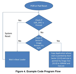
    I don't know what did you modify for the bootloader. Is it possible that your modified bootloader (which was originally designed to download the program image from QSSI flash) is still in download mode? Can you look at the scope capture that the bootloader enters the execution phase where it copies the application to the SDRAM. Please note that the example bootloader as is will rely on the information stored in the sector-0 of the QSSI flash. The secor-0 contains the information about where is the starting address of the SDRAM and the size of the image to copy. Unless you have modified the bootloader to not rely on the sector-0 information, I'm not sure if your modified bootloader is able to copy the application image to the SDRAM and jumps to the external SDRAM address. 

    You can download an image to the QSSI flash memory that has been configured at compile time to
    execute from the EPI address space 0x6000 0000. The image is downloaded from a PC or other
    controller. To load a new image to the QSSI flash, press USR_SW1 when powering up or resetting the
    LaunchPad kit. This causes the bootloader to enter download mode. If the USR_SW1 is not pressed, the
    bootloader reads Sector-0 for a valid image pointer and executes the last image available on QSSI flash. If
    no valid image pointer is found, the bootloader enters download mode and waits for a new image. During

    the execution phase, the bootloader copies the image to the SDRAM memory connected to the EPI
    peripheral. When the image finishes copying, the Cortex-M4 disables the interrupts, updates the
    NVIC_VTABLE register to map to the external address map, and jumps to the external address space
    0x6000 0000. All subsequent code execution occurs in the external address space until the next board
    reset. Figure 4 shows a flow chart of how the code operates.

  • Hi charles Tsai,

                           The issue has been resolved after configuring the correct NVIC_VTABLE register offset(0xE000E100).Please find the entry point function i used for boot from the SDRAM.


    void JumpToEntryPoint(uint_fast32_t ui32StartAddr)
    {
    //
    // Set the vector table to the beginning of the app in SDRAM.
    //
    HWREG(NVIC_VTABLE) = ui32StartAddr;

    #if 0
    __asm(" movw r0, #0x0000\n"
    " movt r0, #0x6000\n"
    " ldr sp, [r0]\n"
    " ldr r0, [r0, #4]\n"
    " bx r0");
    #endif
    //
    // Load the stack pointer from the application's vector table.
    // Load the initial PC from the application's vector table and branch to
    // the application's entry point.
    //
    __asm(" ldr sp, [r0]\n"
    " ldr r0, [r0, #4]\n"
    " bx r0\n");
    }

  • Thank you very much for your support

  • Hi Mani,

      Glad your issue is resolved.